|
100 SERIES
|
|
PRODUCED: YYYY – YYYY
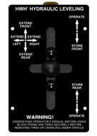
HWH® 100 Series, Lever-Controlled Hydraulic Leveling System
(Four-Lever Control with Separate Indicator Light Panel with Rocker Switch or Toggle Switch)
|
|
PRODUCED: YYYY – YYYY
HWH® 100 Series, Lever-Controlled Hydraulic Leveling System
(Three-Lever Control with Separate Indicator Light Panel with Rocker Switch or Toggle Switch)
|
| CONTROL PANEL |
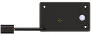
INDICATOR LIGHT PANEL |
 |
 |
 |
 |
 |
|
• 100 Series uses separate indicator light panel >>>
• Single-slot in the control unit bezel plate for each lever.
• Single lever control for each jack.
|
Without HWH® Suspension Air Dump
|
With HWH® Suspension Air Dump
|
With Toggle Switch
(OBSOLETE)
|
|
With Rocker Switch
|
|
• Indicator lights are on a plate mounted SEPARATE from the control unit.
|
|
• Used with straight-acting or kick-down jacks.
|
| 110 SERIES |
|
PRODUCED: YYYY – YYYY
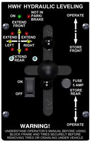
HWH® 110 Series, Lever-Controlled Hydraulic Leveling System
(Four-Lever Control with Integrated Indicator Light Panel with Rocker Switch or Toggle Switch)
(With or Without HWH® Suspension Air Dump)
|
|
PRODUCED: YYYY – YYYY
HWH® 110 Series, Lever-Controlled Hydraulic Leveling System
(Three-Lever Control with Integrated Indicator Light Panel with Rocker Switch or Toggle Switch)
(With or Without HWH® Suspension Air Dump)
|
|
PRODUCED: YYYY – YYYY
HWH® 110 Series, Lever-Controlled Hydraulic Front Jack Equalization System
(Lever Control with Integrated Indicator Light Panel with Rocker Switch or Toggle Switch)
|
| CONTROL PANEL |
 |
 |
|
Without HWH® Suspension Air Dump
|
With HWH® Suspension Air Dump
|
|
• Single lever control for each jack.
• Single slot in the control unit bezel plate for each lever.
• Special control unit & light plate for fifth wheels and travel trailers.
• Used with kick-down or straight-acting jacks.
• Indicator lights are integrated into the slotted bezel plate covering the control unit.
|
| 310 SERIES – TOUCH PANEL |
|
PRODUCED 1995 – 2003
HWH® 310 Series, Touch Panel-Controlled Hydraulic Leveling System
(with MANUAL BI-AXIS® Control)
(Designed for Motorized & Non-Motorized Vehicles)
|
|
PRODUCED: YYYY – YYYY
HWH® 310 Series, Touch Panel-Controlled Hydraulic Leveling System
(with MANUAL BI-AXIS® Control)
(With Hand-Held Pendant Type Controller)
(Designed for Non-Motorized Vehicles) (Straight-Acting Jacks Only)
|
| CONTROL PANEL |
CONTROL BOX |
 |
 |
 |
|
• Without HWH® Suspension Air Dump
|
• With HWH® Suspension Pilot Air Dump
|
• Control Box is 2-3/4″ x 4-1/4″ x 7-1/2″
|
|
• Touch Panel
• Heading: “HWH HYDRAULIC LEVELING”
• Touch panel with a rabbit at the bottom is for vehicles with “Pilot Air Dump”.
• Jacks will retract automatically with “STORE” button.
• Used with kick-down or straight-acting jacks. (Pendant SA jacks only.)
|
| 325 SERIES |
|
PRODUCED: 2003 – PRESENT
HWH® 325 Series, Touch Panel-Controlled Hydraulic Leveling System
(with MANUAL BI-AXIS® Control)
(Long PC Board Series)
|
|
PRODUCED: 2003 – 2004
HWH® 325 Series, Touch Panel-Controlled Hydraulic Leveling System
(with MANUAL BI-AXIS® Control)
(Short PC Board Series)
|
|
PRODUCED: YYYY – YYYY
HWH® 325 Series, Touch Panel-Controlled Hydraulic Leveling System
(with MANUAL BI-AXIS® Control)
(with Hand-Held Pendant Type Controller)
(Designed for Non-Motorized Vehicles)
|
| “SHORT” PC BOARD SERIES | PRODUCED: 2003 – 2004 |
| CONTROL PANEL |
CONTROL BOX |
|
FRONT
|
BACK
|
 |
 |
 |
|
• Touch Panel
• Heading: “HWH HYDRAULIC LEVELING”
• With or Without HWH® Suspension Air Dump
• Touch panel does NOT have “NOT IN PARK/BRAKE” indicator light.
|
• Touch panel has four connectors on back.
• Touch panel has one three-amp fuse on the back.
|
• Short PC Board
• Control box has an 8.5″ x 11″clear plastic cover.
• Electronic (rectangular) level sensor is mounted inside control box.
|
| “LONG” PC BOARD SERIES | PRODUCED: 2003 – Present |
| CONTROL PANEL |
CONTROL BOX |
|
FRONT
|
BACK
|
 |
 |
 |
 |
|
With
HWH® Suspension Air Dump
|
Without HWH® Suspension Air Dump
|
• Touch panel has one five-pin connector on back.
|
• Long PC Board
• Electronic level sensor is mounted inside control box.
• Control box has an 8.5″ x 11″ clear plastic cover.
|
|
• Touch Panel
• Heading: “HWH HYDRAULIC LEVELING”
• “NOT IN PARK/BRAKE” indicator light.
|
| 500 SERIES |
|
PRODUCED: 1988 – 1993
HWH® 500 Series, Computer-Controlled Air Leveling System
(with Four-Point BI-AXIS® Touch Panel Control)
|
|
PRODUCED: YYYY – YYYY
HWH® 500 Series, Computer-Controlled, Air Leveling System
(with Three-Point Touch Panel Control)
|
|
PRODUCED: YYYY – YYYY
HWH® 500 Series, Computer-Controlled Air/Hydraulic Leveling System
(with BI-AXIS® Touch Panel Control)
|
|
PRODUCED: YYYY – YYYY
HWH® 500 Series, Computer-Controlled Hydraulic Leveling System
(with BI-AXIS® Touch Panel Control)
|
| CONTROL PANEL |
CONTROL BOX |
|
FRONT
|
BACK
|
 |
 |
 |
|
• Touch Panel
• Heading: “HWH COMPUTERIZED LEVELING”.
|
• Touch panel has a forty-pin connector on back.
|
• Glass or blade style fuses may be found in a 500 Series control box.
• Control box is 3-1/2″ x 9″ x 14-1/2″.
|
|
• Used for Air Leveling or combination Air/Hydraulic Leveling.
• Connecting cable between the control box and touch panel is a 2″ wide, flat, forty-pin ribbon cable.
|
| 510 SERIES (510M SERIES – AP8073) |
|
PRODUCED: 1990-1/2 – 1993
HWH® 510 Series, Computer-Controlled Hydraulic Leveling System
(with BI-AXIS® Touch Panel Control)
|
| CONTROL PANEL |
CONTROL BOX |
| FRONT |
BACK |
 |
 |
 |
|
• Touch Panel
• Heading: “HWH COMPUTERIZED LEVELING”
|
Touch panel has either
a forty-pin connector on back
(OR) an eight-wire connector on back.
|
Control box is 2-3/4″ x 4-1/4″ x 6-1/2″
|
|
• Connecting cable between the control box and touch panel was a
2″ wide, flat, 40 pin ribbon cable (early models) or a 3/8″ wide, flat, eight-wire ribbon cable.
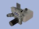
• The hydraulic pump and manifold are separate units connected with a high pressure hose and return line.
|
| 600 SERIES |
|
PRODUCED: 1988-1993
HWH® 600 Series, Computer-Controlled Air Leveling System
(with BI-AXIS® Touch Panel Control)
|
|
PRODUCED: YYYY – YYYY
HWH® 600 Series, Computer-Controlled Air/Hydraulic Leveling System
(with BI-AXIS® Touch Panel Control)
|
|
PRODUCED: YYYY – YYYY
HWH® 600 Series, Computer-Controlled Hydraulic Leveling System
(with BI-AXIS® Touch Panel Control)
|
| CONTROL PANEL |
CONTROL BOX |
| FRONT |
BACK |
 |
 |
 |
|
• Touch Panel
• Heading: “HWH COMPUTERIZED LEVELING”.
• STORE function.
• Air dump optional.
• Air systems have DUMP & RAISE feature.
|
Touch panel has an eight-wire connector on back.
|
• Only blade style fuses will be found in a 600 Series control box.
• Control box is 3-1/2″ x 9″ x 14-1/2″.
|
|
• Connecting cable between the control box and the touch panel is 3/8″ wide, flat, eight-wire ribbon cable.
• Used for Air Leveling, Hydraulic Leveling, or combination Air/Hydraulic leveling.
|
| 610 SERIES |
|
PRODUCED: 1992 – 1993
HWH® 610 Series, Computer-Controlled Hydraulic Leveling System
(with BI-AXIS® Touch Panel Control)
(NON-Central Ground)
|
|
PRODUCED: 1993 – 2003
HWH® 610 Series, Computer-Controlled Hydraulic Leveling System
(with BI-AXIS® Touch Panel Control)
(Central Ground)
|
610 SERIES – NON-CENTRAL GROUND
PRODUCED: 1992-1993 |
| CONTROL PANEL |
CONTROL BOX |
| FRONT |
BACK |
 |
 |
 |
|
• Touch Panel
• Heading: “HWH COMPUTERIZED LEVELING”
• STORE function.
|
Touch panel has an eight-wire connector on back.
|
Control Box is 2-3/4″ x 4-1/2″ x 6-1/2″.
|
|
• Connecting cable between the control box and touch panel is a 3/8″ wide, flat, eight-wire ribbon cable.
• The warning switch harness at each jack has one plug only. It may be a one-wire or two-wire connector.
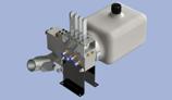
• The pump and manifold are one assembly.
|
610 SERIES – CENTRAL GROUND
PRODUCED: 1993 – 2003 |
| CONTROL PANEL |
CONTROL BOX |
| FRONT |
BACK |
 |
 |
 |
|
• Touch Panel
• Heading: “HWH COMPUTERIZED LEVELING”.
|
Touch panel has one eleven-pin connector on back.
|
• Control Box is 2-3/4″ x 4-1/2″ x 7-1/2″.
• Central ground.
|
|
• Connecting cable between the control box and touch panel is an eleven-pin cable assembly.
• The warning switch harness at each jack has two plugs, one single-wire and one two-wire connector.
• The pump and manifold are one assembly.
|
| 625 & 625S SERIES |
|
PRODUCED: 2003 – PRESENT
HWH® 625 Series, Computer-Controlled Hydraulic Leveling System
(with BI-AXIS® Touch Panel Control)
(Programmable Sensing Unit)
|
|
PRODUCED: 2006
HWH® 625S Series, Leveleze® Single-Step Computer-Controlled Hydraulic Leveling System
(with BI-AXIS® Touch Panel Control)
(Programmable Sensing Unit)
|
625 SERIES
PRODUCED: 2003 – PRESENT |
| CONTROL PANEL |
CONTROL BOX |
| FRONT |
BACK |
 |
 |
 |
|
• Touch Panel
• Heading: “HWH COMPUTERIZED LEVELING”
• Lower middle green indicator light is labeled “TRAVEL MODE” not “TRAVEL”.
|
Five-pin connector on back.
|
• Control box has an 8″ x 11″ clear plastic cover.
• Control box is mounted to the pump tray.
• Electronic programmable level sensor is mounted inside control box.
|
|
• The jack warning switch plugs are grey.
• Used for hydraulic leveling only.
|
625S (SINGLE STEP) SERIES
PRODUCED: 2006 |
| CONTROL PANEL |
CONTROL BOX |
| FRONT |
BACK |
 |
 |
 |
|
• Touch Panel
• Heading: “HWH COMPUTERIZED LEVELING”
• Touch Panel has an outline around the manual UP and DOWN arrows.
• Lower middle green indicator light is labeled “TRAVEL MODE” not “TRAVEL”.
|
• Touch panel has a five-pin connector on back.
• Six-pin connector may not be present on back of touch panel.
|
• Control box has an 8″ x 11′ clear plastic cover.
• Control box is mounted to the pump tray.
• Electronic programmable level sensor is mounted inside control box.
|
|
• Jack warning switch plugs are grey.
• Used for hydraulic leveling only.
|
| 680 SERIES |
|
PRODUCED: 1997 – 2002
HWH® 680 Series, Computer-Controlled Hydraulic Leveling System
(with BI-AXIS® Touch Panel Control)
|
|
PRODUCED: YYYY – YYYY
HWH® 680 Series, Computer-Controlled Air Leveling System
(with BI-AXIS® Touch Panel Control)
|
|
PRODUCED: YYYY – YYYY
HWH® 680 Series, Computer-Controlled Air/Hydraulic Leveling System
(with BI-AXIS® Touch Panel Control)
|
| CONTROL PANEL |
CONTROL BOX |
| FRONT |
BACK |
 |
 |
 |
|
• Touch Panel
• Heading: “HWH COMPUTERIZED LEVELING”
|
Touch panel has an eight-wire connector on back.
|
• Control box is 3-1/2″ x 14-1/2″ x 19″.
• Control box is 3-1/2″ deep.
|
|
• Used for Air Leveling or combination Air/Hydraulic Leveling
• Connecting cable between the control box and touch panel is a 2/8″ wide, flat, eight-wire ribbon cable.
|
| 725 SERIES |
|
PRODUCED: YYYY – PRESENT
HWH® 725 Series, Computer-Controlled Hydraulic Leveling System
(with BI-AXIS® Touch Panel Control) (Kick-Down Jacks)
|
|
PRODUCED: YYYY – YYYY
HWH® 725S Series, Leveleze® Single-Step Computer-Controlled Hydraulic Leveling System
(with BI-AXIS® Touch Panel Control) (Straight-Acting Jacks)
|
|
PRODUCED: YYYY – YYYY
HWH® 725S Series, Leveleze® Single-Step Computer-Controlled Hydraulic Leveling and Landing Gear System
(with BI-AXIS® Touch Panel Control) (Straight-Acting Jacks)
|
| CONTROL PANEL |
SENSING UNIT & I/O CONTROL MODULE
(NO CONTROL BOX) |
| FRONT |
BACK |
 |
 |
Potted Electronic Sensing Unit (above)

Potted Multiplexed Input Output Module (“MIOM”) (above)
|
|
• Touch Panel
• Heading: “HWH COMPUTERIZED LEVELING”
• Touch panel “manual” operations enclosed with white outline.
• Lower middle green indicator light is labeled “TRAVEL MODE” not “TRAVEL”.
|
• Touch panel has a five-pin connector on back.
• Touch panel has a ________ on back.
|
• MIOM mounted on pump.
• MIOM replaces typical control box.
• Potted electronic (rectangular) sensing unit is remote-mounted with three screws and three springs.
|
|
• All 725 Series are Single-Step, unless they have kick-down jacks.
• Can have Auxiliary Hand-Pump Control.
• Use for Hydraulic leveling.
|
| 2000 SERIES (PRODUCED: 2001 – PRESENT) |
|
PRODUCED: YYYY – YYYY
HWH® 2000 Series, Computer-Controlled Hydraulic Leveling and/or Landing Gear System
(with BI-AXIS® Touch Panel Control) (for Non-Motorized Towable Vehicles)
|
|
PRODUCED: YYYY – YYYY
HWH® 2000 Series, Computer-Controlled Hydraulic Leveling System
(with BI-AXIS® Touch Panel Control)
|
|
PRODUCED: YYYY – YYYY
HWH® 2000 Series, Computer-Controlled Air Leveling System
(with BI-AXIS® Touch Panel Control)
|
|
PRODUCED: YYYY – YYYY
HWH® 2000 Series, Computer-Controlled Air/Hydraulic Leveling System
(with BI-AXIS® Touch Panel Control)
|
|
PRODUCED: YYYY – YYYY
HWH® 2000S Series, Leveleze® Single-Step Computer-Controlled Air Leveling System
(with BI-AXIS® Touch Panel Control)
|
|
PRODUCED: YYYY – YYYY
HWH® 2000S Series, Leveleze® Single-Step Computer-Controlled Hydraulic Leveling System
(with BI-AXIS® Touch Panel Control)
|
|
PRODUCED: YYYY – YYYY
HWH® 2000 Series, Computer-Controlled Precision Hydraulic Leveling System
(with BI-AXIS® Touch Panel Control, for Motorized Vehicles)
|
|
PRODUCED: YYYY – YYYY
HWH® 2000 Series, Computer-Controlled Precision Hydraulic Leveling System
(with BI-AXIS® Touch Panel Control, for Non-Motorized Vehicles)
|
| CONTROL PANEL |
SENSING UNIT & CONTROL BOX |
| FRONT |
BACK |
 |
 |
 |
|
• Touch Panel
• Heading: “HWH COMPUTERIZED LEVELING”
• Lower Middle green indicator light is labeled “TRAVEL MODE” not “TRAVEL”.
|
Touch panel has a five-pin connector on back.
|
• Control box has an 8″ x 11″ clear plastic cover.
• Control boxes are stacked.
• Electronic (rectangular) level sensor is mounted inside of control box.
|
|
• Use for Air Leveling or combination Air/Hydraulic Leveling.
• Can have Auxiliary Hand-Pump Control.
|