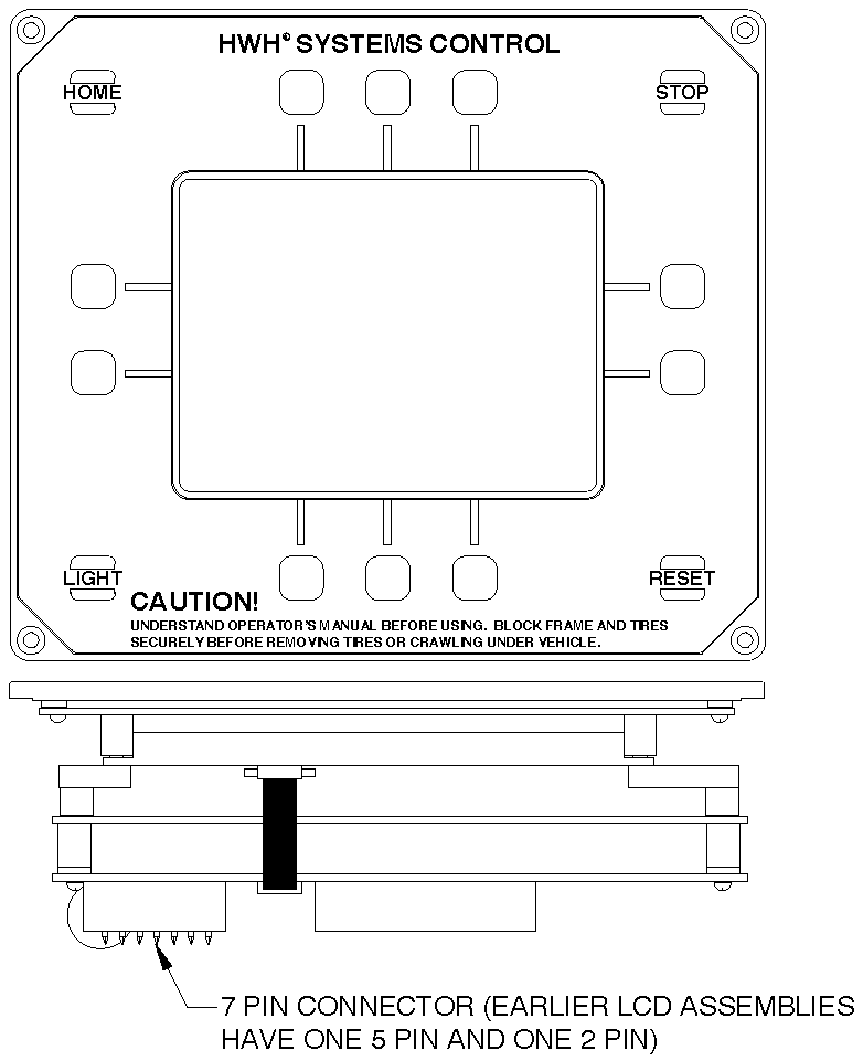
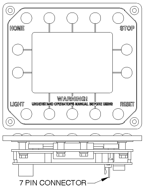
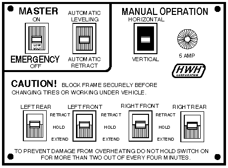
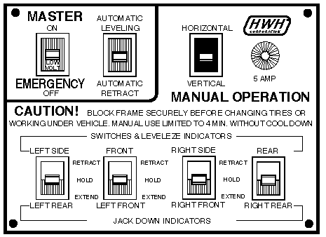
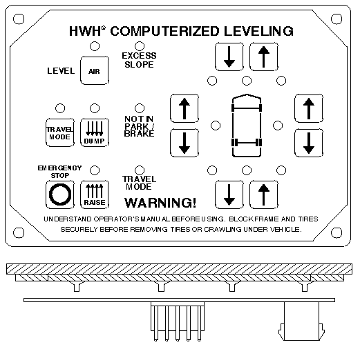
400 Series (Paddle Switch): 1985 – 1992
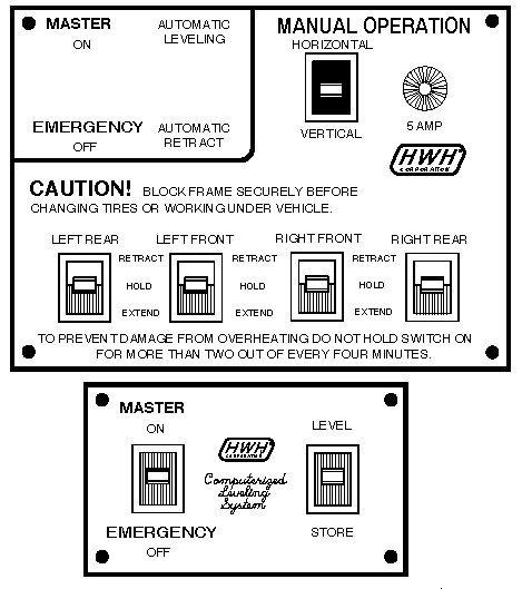
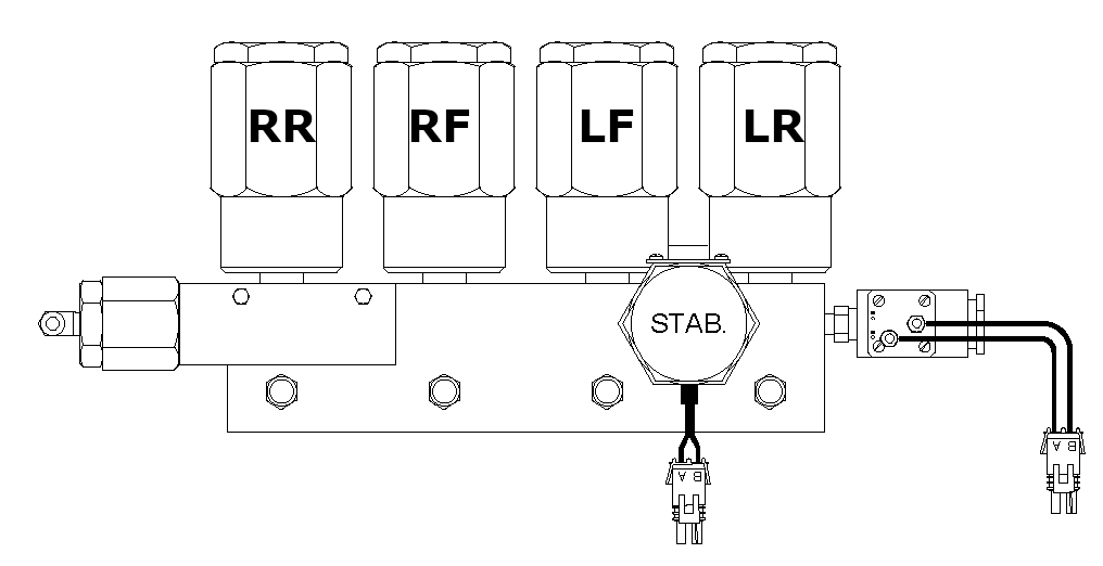
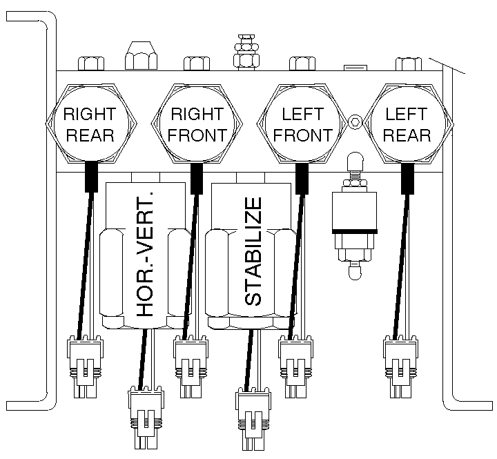
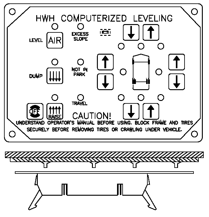
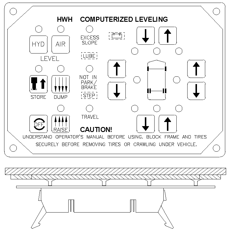
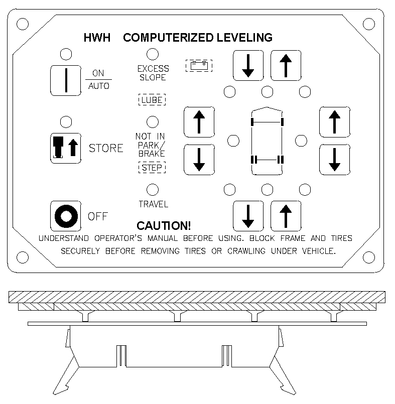
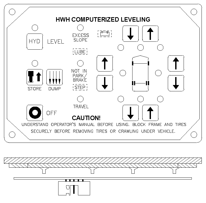
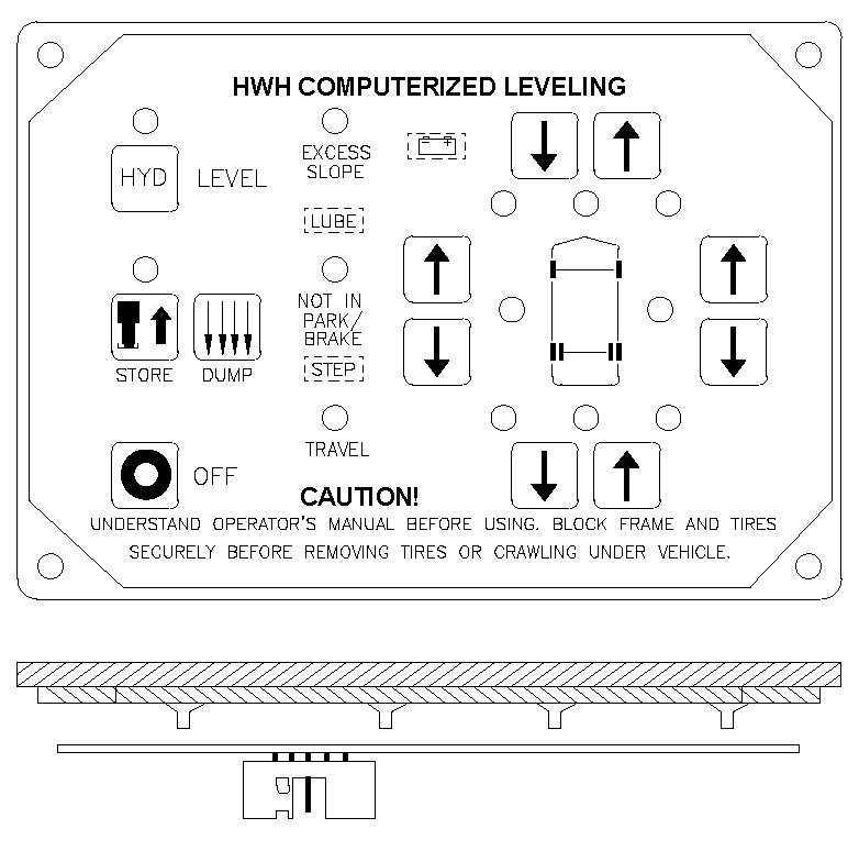
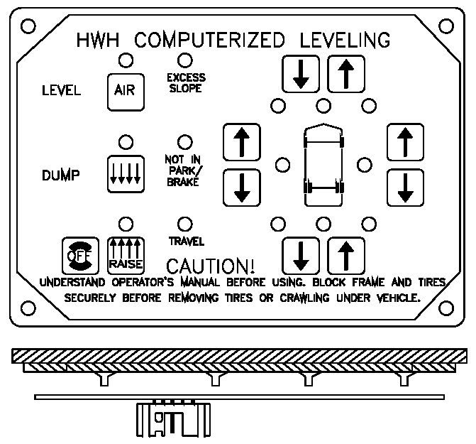
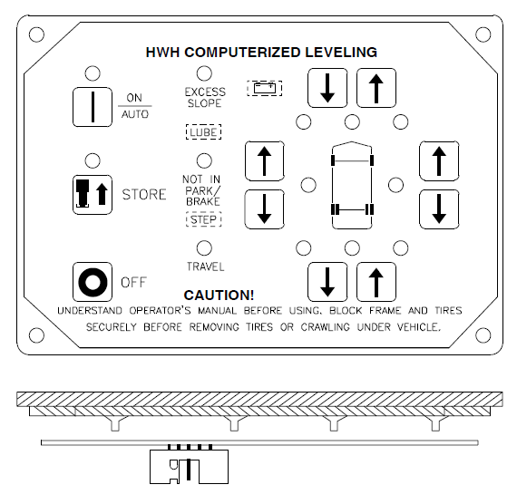
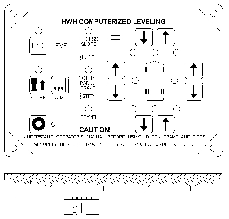
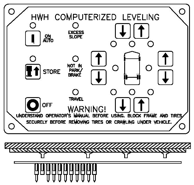
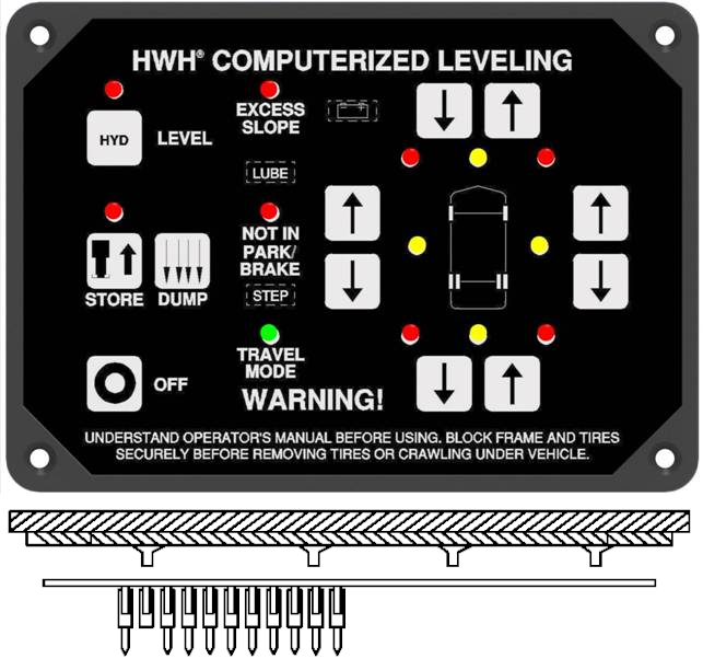
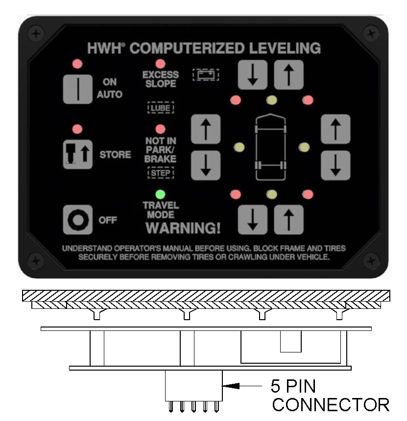
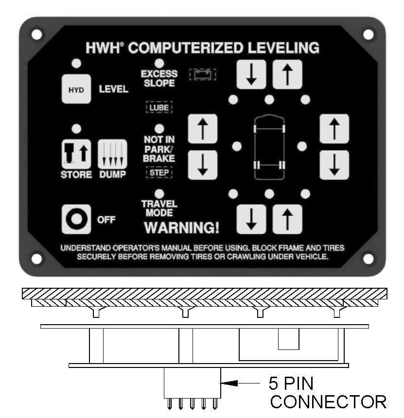
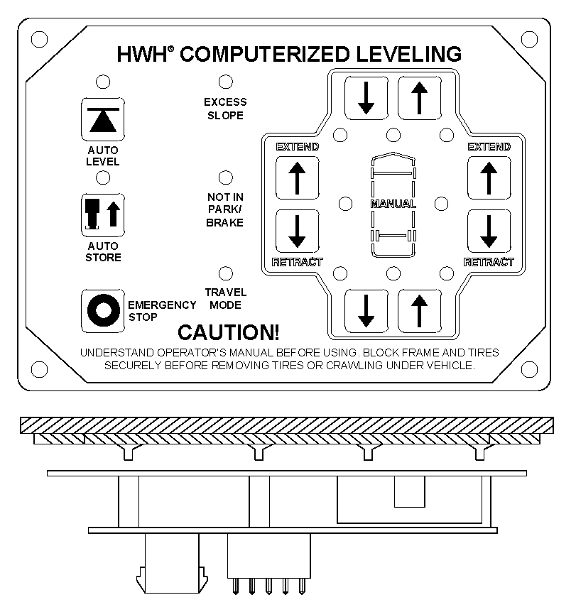
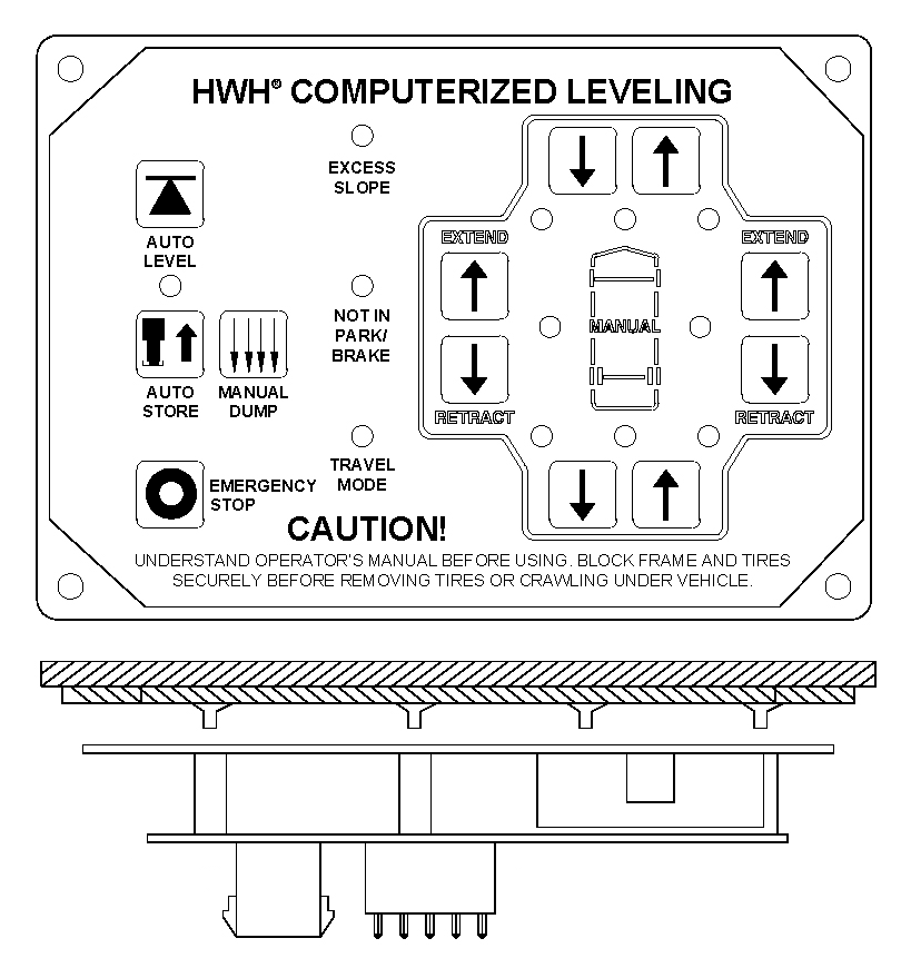
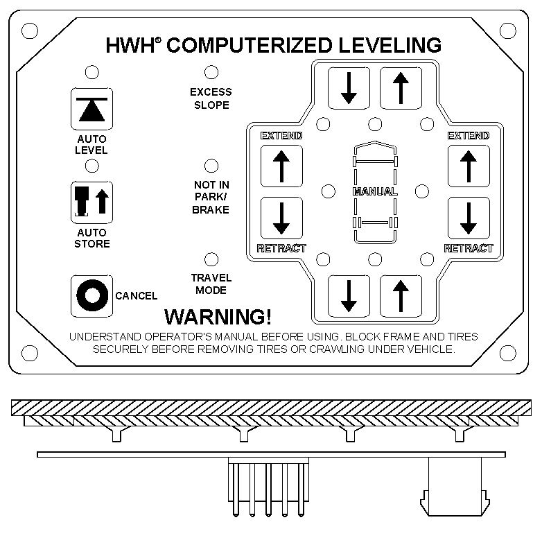
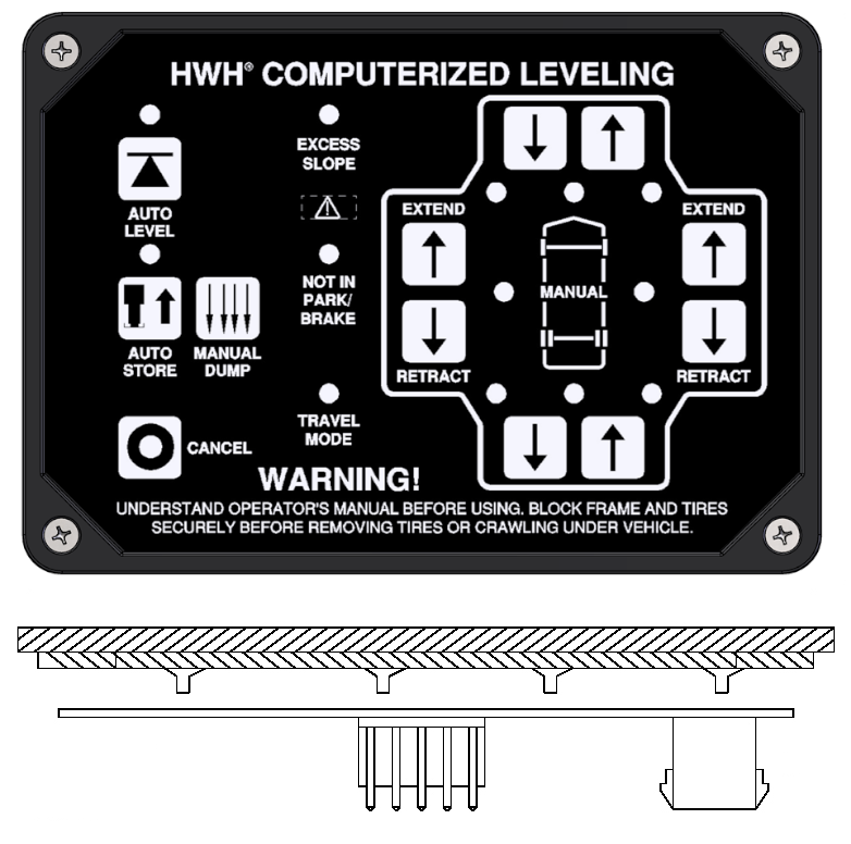
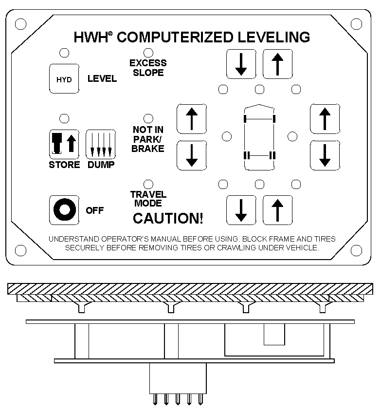
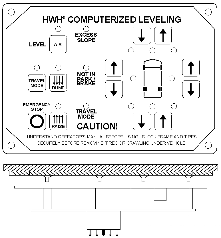
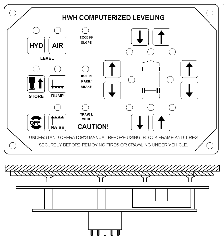
The 400 Series or Paddle Switch System, as it is commonly referred to, was the first fully automatic (computerized) leveling system produced in the industry. It’s nickname comes from the paddle type switches used on the control panel. It can be used with either straight-acting or kick-down style jacks. The system can be used automatically or there is also manual control. The most common system used individual jack control meaning only one jack at a time was used for leveling although there were a couple systems with special programs. The manual switches operated one jack at a time. The other system was the first Bi-Axis® leveling system meaning it used 2 jacks at a time for leveling. The manual switches operated pairs of jacks, both front, both rear, left side jacks or right side jacks. Each system used a different hydraulic manifold. This system was not park brake dependent to operate. Like the 200 series Joystick system, this system used a ground signal to control the pump relay. It also used a ground signal to control the solenoid valves. 400 series solenoid valves are not interchangeable with any other solenoid valves produced by HWH. The two types of panels look very similar but the labeling of the manual switches is different. Some panels have a remote ON/OFF switch and Auto Level/Retract switch panel. This panel came in single jack or Bi-Axis® control. Systems with straight acting jacks do not have a Horizontal/Vertical switch or valve.
|
Single Jack Control
|
Bi-Axis® Control
|
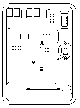
Remote Switch Panel
|
| Labeling of the Manual Switches is Different |
||
|
Single Jack Control
|
Bi-Axis® Control
|
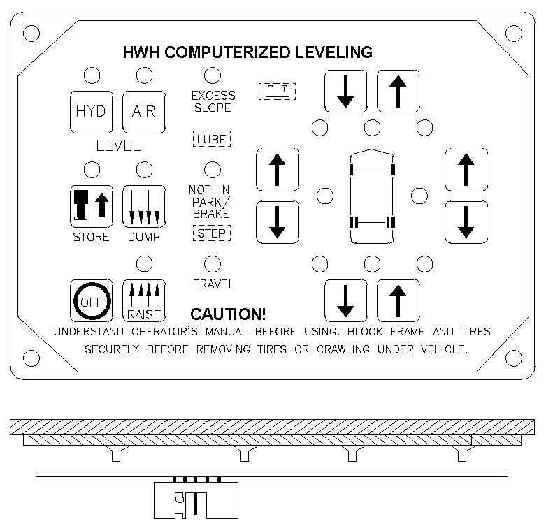
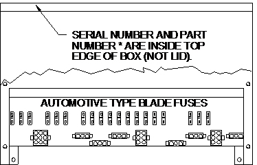
500 SERIES: 1988 – 2000
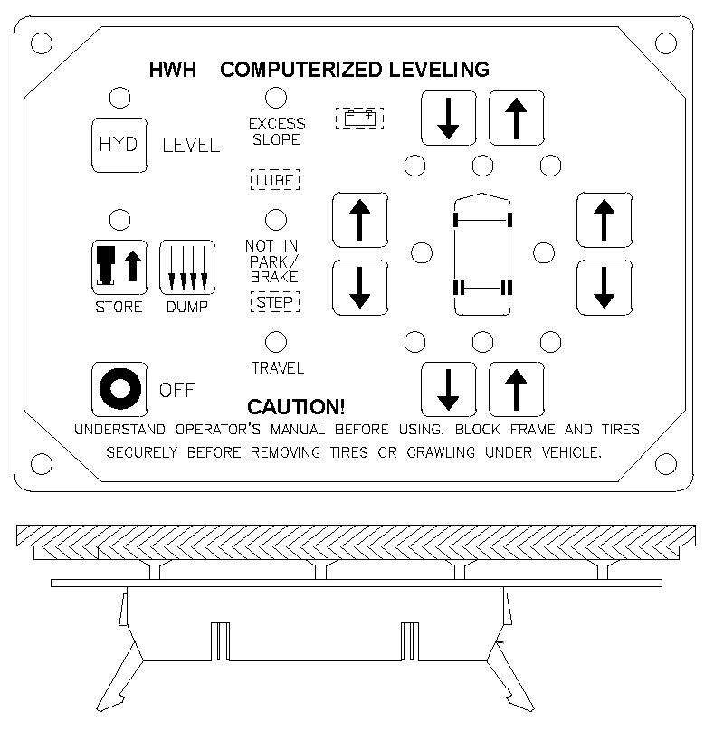
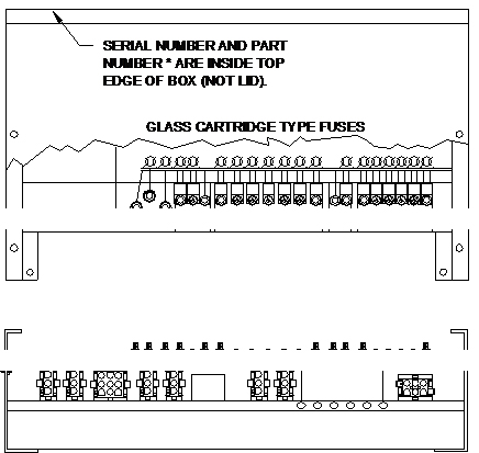
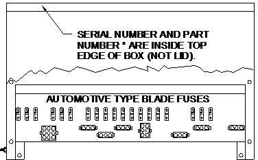
This was the first fully automatic (computerized), touch panel controlled system and the first to use the vehicle air suspension for leveling. This system could do air leveling only, have the option of air or hydraulic leveling or do hydraulic leveling only. The control box was a 14.5″ x 9.0″ x 3.5″ aluminum box. The early 500 series control boxes used the glass automotive fuses but were then switched to the automotive blade fuses. If the system has both air and hydraulic leveling capabilities, only one style of leveling can be used at a time. There are quite a few different control boxes and touch panels but this is an obsolete system and the control boxes are no longer available but can be sent in to be repaired. The 500 series and 600 series systems are very similar in appearance so the main identifying feature for the 500 system is the 2″ wide, 40 pin ribbon cable between the control box and the touch panel. The 600 series uses a 3/8″ wide cable. The 500 series hydraulic manifold looks like the 400 series B-Axis® hydraulic manifold but uses different solenoid valves and uses a flow switch instead of a pressure reducing valve. Refer to the 510 Series for a view of the hydraulic manifold.
|
500 Series Touch Panel
|
500 Series Touch Panel
|
500 Series Touch Panel
|
| |———————————- 40 Pin Connector ———————————-| | ||
|
500 Series Control Box
|
500 Series Control Box
|
510 SERIES: 1990 ½ – 1992
This touch panel controlled system is an extension of the 500 series system and replaced the 400 series Paddle Switch system as the standard automatic leveling system. It was only available as a hydraulic leveling system. It was available with suspension air dump control and could be used with straight-acting or kick-down style jacks. Kick-down jacks required two hydraulic hoses for each jack, one for the kick-down actuator and one for the main jack. The early 510 series system used the same style 40 pin ribbon cable to connect the touch panel and control box. The later 510 series systems used a 3/8″ wide, 8 wire modular cable. The later touch panel uses a 10 pin connector while the control box uses a telephone style connecter. The touch panel, cables and control boxes are NOT interchangeable. The 510 control box is a an aluminum box that is 2.75″ x 4.25″ x 7.0″. The 510 control box is no longer available but most likely can be repaired if needed. The hydraulic manifold for the 510 series system is the same as the 500 series manifold, using a flow switch and eliminating the horizontal/vertical valve when used with straight-acting jacks.
|
510 Series Touch Panel
|
510 Series Touch Panel
|
|
510 Series Control Box
|
510 Series Control Box
|
|
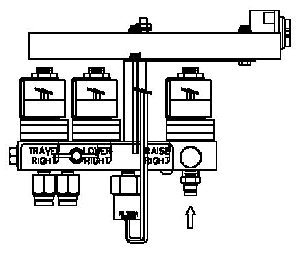
510 Series Hydraulic Manifold
|
|
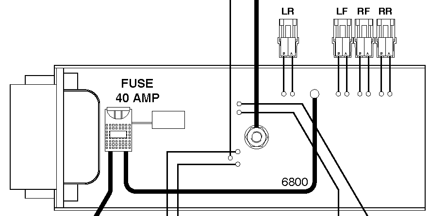
600 SERIES: 1992 – 1998
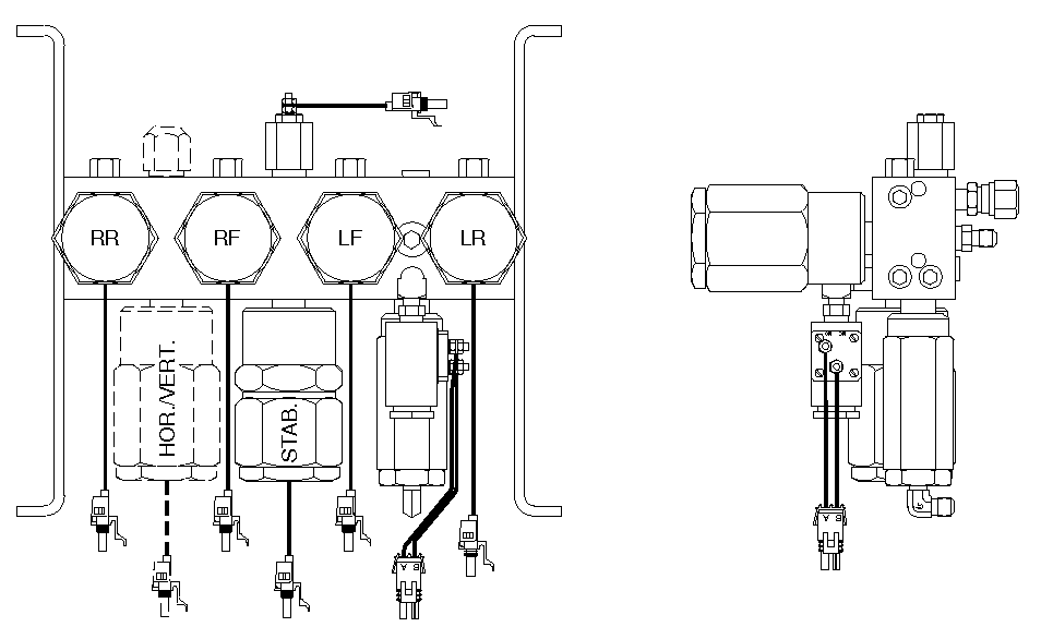
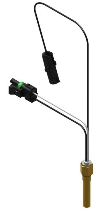
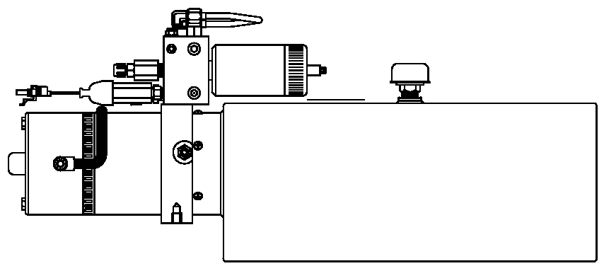
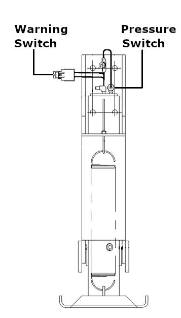
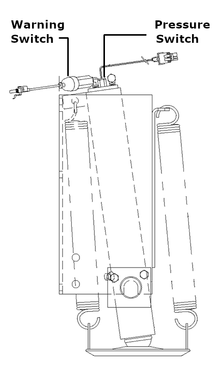
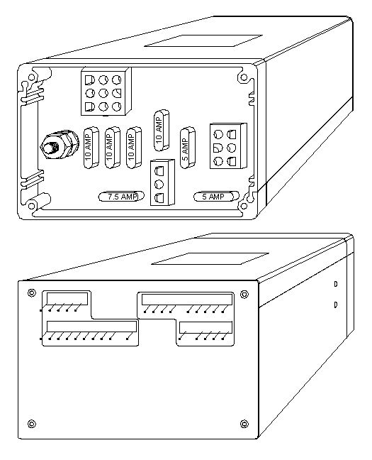
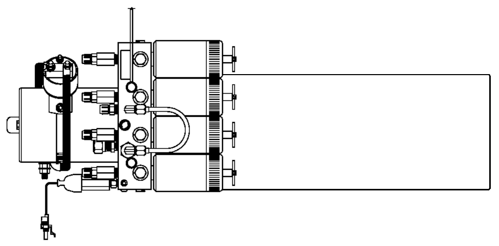
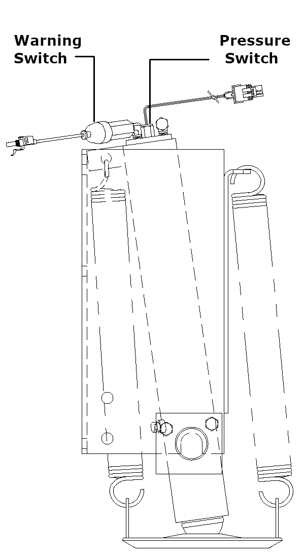
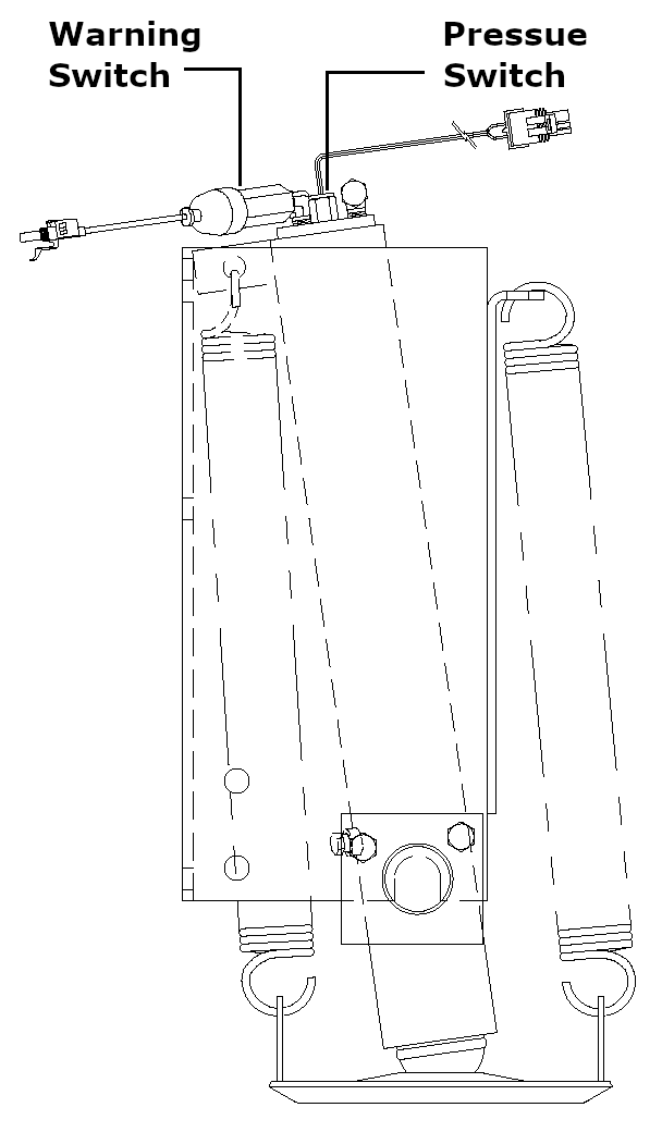
The 600 series system is a touch panel controlled, automatic system. This system could do air leveling only, have the option of air or hydraulic leveling or do hydraulic leveling only. The control box was a 14.5″ x 9.0″ x 3.5″ aluminum box. The control box and touch panels look the same as the 500 series system. The difference is the cable between the control box and the touch panel. The 600 series cable is a 3/8″ wide, 8 wire modular cable. The air leveling side of the 600 series is pretty much the same as the 500 series but the 600 series hydraulic leveling system is totally different. Except for some Blue Bird coaches, the hydraulic manifold was mounted directly to the pump. It no longer used a horizontal/vertical valve if the vehicle was equipped with kick-down jacks. The solenoid valves are round with one wire. If replaced later, the valve will have two wires with an adaptor that supplies a ground for the valve. Each jack will have a pressure switch and the warning switch is a three wire switch. There is only one hose going to each jack, straight-acting or kick-down style jacks. 600 series control boxes are no longer available but can be sent to HWH for repair if necessary.
|
600 Series Touch Panel
|
600 Series Touch Panel
|
600 Series Touch Panel
|
|
600 Series
|
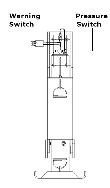 |
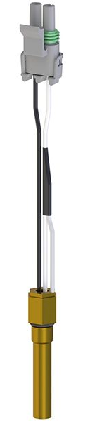
Warning Pressure
|
|
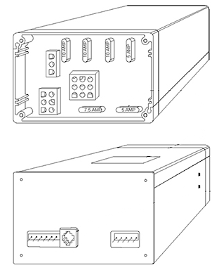
600/610/610 CG Series Power Unit
|
||


610 SERIES: 1992-1993
The 610 series system was a touch panel controlled, automatic hydraulic only leveling system and was designed to streamline the automatic leveling system and make it more installer friendly. Like the 600 series, the manifold was attached directly to the pump and used only four solenoid valves, one for each jack. The horizontal/vertical valve and the stabilize valve were eliminated. The original solenoid valves were round and had only one wire. If replaced later, the valve would have two wires with an adaptor that supplies a ground for the valve. Kick-down style jacks now only used one hose per jack. Each jack has a pressure switch which was used to stabilize the vehicle after leveling. A three wire warning switch was used. The control boxes and touch panels looked exactly like the 510 control box, 2.75″ x 4.25″ x 7.0″. They use the same 3/8″ cable between the box and touch panel. The boxes are not interchangeable between the two systems but several touch panels are. Except for the control boxes, the 610 system uses the same hydraulic equipment as the 600 series systems. The control boxes are not available as new or re-manufactured but can be sent in for repair and return.
|
610 Series Touch Panel
|
610 Series Touch Panel
|
|
610 Series
|
 |
Warning Pressure
|
|
600/610/610 CG Series Power Unit
|
610 CG (Central Ground) SERIES: 1993-2003
The 610 CG was a touch panel controlled, automatic, hydraulic only leveling system. This system replaced the 610 Series system and while the hydraulics were basically the same, the electronics were totally different. It was available with or without air dump and around 1995 with pilot air dump as it became available. The touch panel looked the same but used a different style cable so touch panels were not interchangeable with the original 625. Operationally, the systems were the same and the basic leveling programs were very similar. The control box was similar but 1″ longer and used relays instead of transistors to control the different system components. The harness for the jacks had a separate two wire Packard connector for the warning switch with a single pin Packard connector for the pressure switch. The same jack pressure switch was used but a two wire warning switch without any resistors was now used instead of the three wire switch. The same level sensing unit and pump/manifold arrangement was used. The touch panel cable was a cable assembly instead of the 3/8″ modular cable. The touch panels are still available. The control boxes are not available as new or re-manufactured but can be sent in for repair and return.
|
610 CG Series Touch Panel
|
610 CG Series Touch Panel
|
|
610 CG Series
|
 |
Warning Pressure
|

|
600/610/610 CG Series Power Unit
|

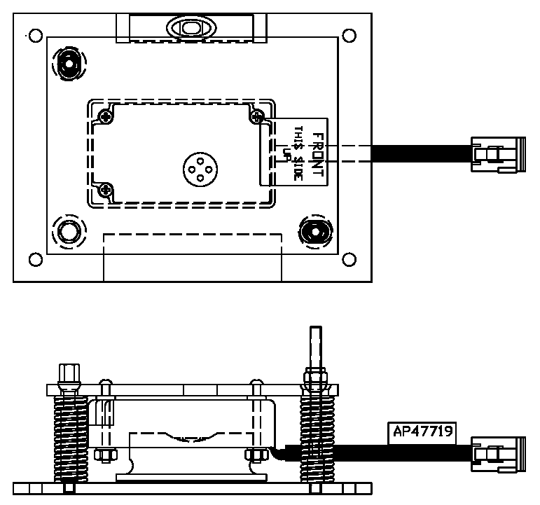
625 SERIES: 2003-2006
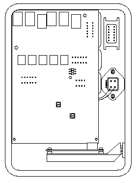
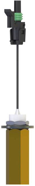
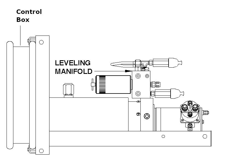
The 625 series is a hydraulic leveling only system. Although available with a remote mounted control box, most systems have the control box mounted as part of the power unit. This system also incorporated the new electronic level sensing unit. The sensing unit was mounted in the control box and required the sensing unit be programmed according to the orientation of the power unit so the system could identify the front of the vehicle for leveling purposes. For O.E.M. installations, HWH could program the sensing unit during production as long as the orientation of the power unit was predetermined by the O.E.M. For aftermarket installations and sensing unit replacement, a programmable level sensing unit was used. Two sets of jumpers on the sensing unit panel were used for programming the orientation of the power unit. A third set of jumpers allowed the sensing unit to program the suspension type, spring or air. The system can be used with straight-acting or kick-down style jacks and uses the same jack pressure switches as the 610 CG Series systems. It can be used with or without air dump. The control box has a clear Plexiglas cover and is equipped with LEDs that can be used to diagnose issues with the system. The control boxes and touch panels are no longer available as new or re-manufactured units but can be sent to HWH for repair and return.
|
625 Series Touch Panel
|
625 Series Touch Panel
|
|
625 Series
|
 |
Warning Pressure
|

|
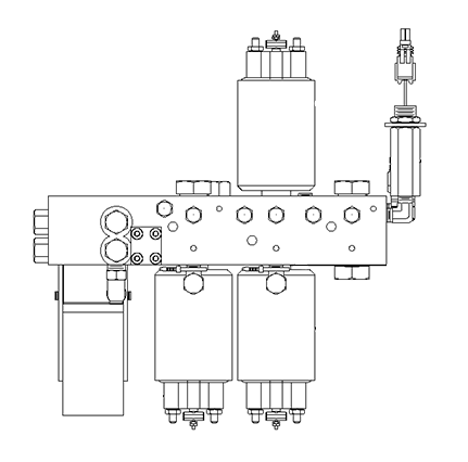
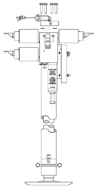
625 Series Power Unit
|
625S SERIES: 2006-2010
The 625S series equipment looks much like the 625 series. The only visible difference is the touch panel. The 625 and 625S touch panels and control boxes are NOT interchangeable. The 625S system is a single step/one touch system. This means there is no “ON” button to turn the system on. Anytime the ignition is on and the park brake is set, the system is ready to operate. Pushing the “Level” button starts the automatic leveling sequence or the manual “UP” and “DOWN” arrow buttons can be used as long as an automatic leveling sequence has not been started. The control boxes and touch panels are no longer available as new or re-manufactured units but can be sent to HWH for repair and return.
|
625S Series Touch Panel
|
625S Series Touch Panel
|
|
625S Series
|
 |
Warning Pressure
|


|
625S Series Power Unit
|

680 SERIES: 1997-2001
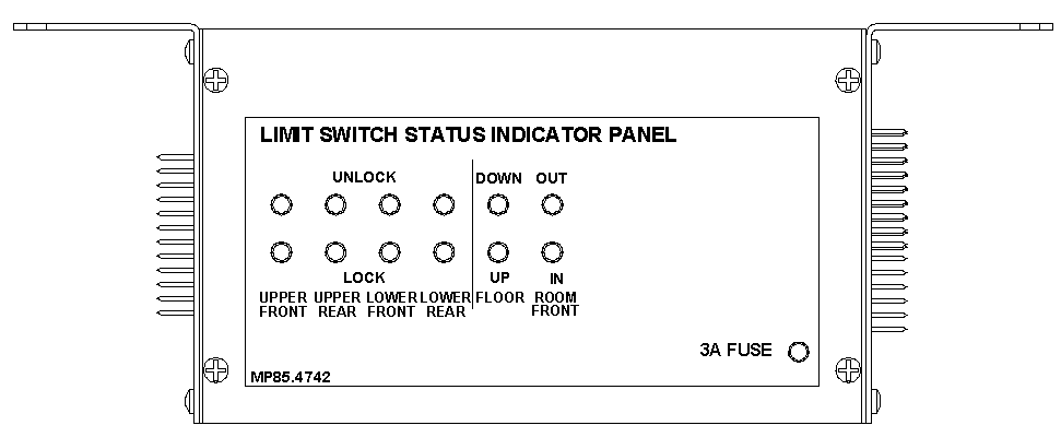
The 680 series system was developed to take care of vehicles that incorporated room extensions with hydraulic room locks air seals. These vehicles always locked with the rooms in and some with the rooms in and out. It could be used with air and/or hydraulic leveling. The control box was large and fairly complex. It was approximately 14″ x 19″ x 3″. For leveling, the box incorporated PC boards that were similar to the boards used in the 600 series system and was computerized. For room extension control, the boards used relay logic with no type of processor. The hydraulic leveling, air leveling and basic room extension equipment was the same as other systems. The main difference was the hydraulic locks and air seals. The locks would extend a pin into a receiver to lock the room. This required the system to recognize when the lock pin was extended or retracted and when the room was fully extended or retracted. If not done properly, the locks could extend when it shouldn’t and damage the room or not let the room extend or retract. Locks and rooms were equipped with limit switches that would send information to the control box indicating the room was extended or retracted and the position of the lock pin, in the lock or unlocked position. Limit switch light boxes were developed that allowed the wiring for room and lock position limit switches to be routed to one central point. These boxes had indicator lights that would show the position of all the limit switches used for a particular room. This helped with the diagnostics for room extension issues. The relay boards for the rooms in the control box also were equipped with LED lights to help with diagnostics. The 680 control boxes and the limit switch light boxes are no longer available as new or re-manufactured but can be sent to HWH for repair and return.
Refer to the 600 Series and 610 Series for views of touch panels and hydraulic equipment. The 680 Series used the same 3 wire warning switch as the 600 and 610 Series systems.
|
680 Series Control Box
|
680 Series
|
700 SERIES: 2011-2018
The 700 Series system is an air leveling only multiplex system. The controls consist of the touch panel, which has the controlling processor and a MIOM at each air manifold. MIOM stands for Multiplexed Input Output Module. The touch panel makes all of the decisions and the MIOMs control the valves and send information, such as from pressure switches and the level sensing unit, to the touch panel. The air manifolds are basically the same as used with the 500 and 600 air leveling systems. They each have 2 lower, 2 raise and 2 travel valves, one set for each side of the vehicle at the front, rear and tag is so equipped. The manifolds will also have pressure switches to monitor air bag pressure and usually the rear manifold will have a pressure switch which monitors vehicle system air pressure. The MIOMs are mounted directly to the air leveling manifolds. The touch panels and MIOMs are still available for repair but the replacement MIOM may have a different connector and will need a special pigtail to adapt the new MIOM to the existing harness.
|
700 Series
|
700 Series Air Leveling
|
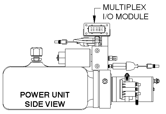
725 SERIES: 2010-PRESENT
The 725 Series system is a hydraulic leveling only multiplex system. The controls consist of the touch panel, which has the controlling processor and a MIOM that is mounted to the top of the leveling system hydraulic manifold. MIOM stands for Multiplexed Input Output Module. There is no control box. The touch panel makes all the decisions and the MIOM controls the valves and sends information, such as from pressure switches and the level sensing unit, to the touch panel. There are different touch panels and MIOMs depending on the type of HWH equipment (other than leveling system components) that are being used and how the systems operate. All of the hydraulic leveling system equipment is basically the same as used for the 625/625S systems. The touch panels and MIOMs are still available for repair but the replacement MIOM may have a different connector and will need a special pigtail to adapt the new MIOM to the existing harness.
|
725 Series Touch Panel
|
725 Series Touch Panel
|
 |
Warning Pressure
|
|
725 Series MIOM
|
725 Series Power Unit
|
2000 SERIES: 2000-2016
The 2000 Series system was based on CAN technology. (Controller Area Network) The CAN technology allowed input/output modules to be located anywhere in the vehicle. The modules were connected by one main trunk harness that connected to a “mother board”. The mother board controlled the system. Multiple pieces of equipment could be controlled from one central point including air and/or hydraulic leveling systems, room extensions with or without locks and air seals, steps and gen slides, to name a few. The 2000 Series system was also the first system used with double acting jacks. This could be for motorized or towable vehicles. The touch panel was just another “module” in the system. The mother board module and the input/out put modules, referred to as “rings”, were 8 ½ inches by 11 inches. Like the 625 systems, the PC boards for the modules were equipped by LEDs that were used for diagnostics. There could be a single ring or there could be an assembly with as many as 3 rings. The 2000 Series system was primarily used for vehicles with air or a combination air and hydraulic leveling system and vehicles incorporating hydraulic room locks and/or room air seals. All of the leveling equipment, hydraulic or air, and room, room locks and air seals was the same as used for the 625 and 680 systems. 2000 Series module assemblies had a part number sticker on the outside of the assembly which would be for the complete assembly and each ring had it’s individual part number on the inside of the ring. Single ring modules usually had the sticker on the outside of the module. 2000 Series CAN touch panels look like the 625/625S touch panels but are not interchangeable. Make sure you have the correct panel or contact HWH for assistance. The modules and touch panels are no longer available as new or re-manufactured units but can be sent to HWH for repair and return.
|
2000 Series Touch Panel
|
2000 Series Touch Panel
|
|
2000 Series Touch Panel
|
|
|
2000 Series Control Box
|
2000 Series Control Box
|
|
2000 Series Control Box
|
|
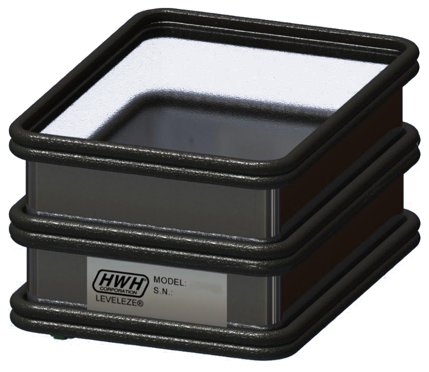
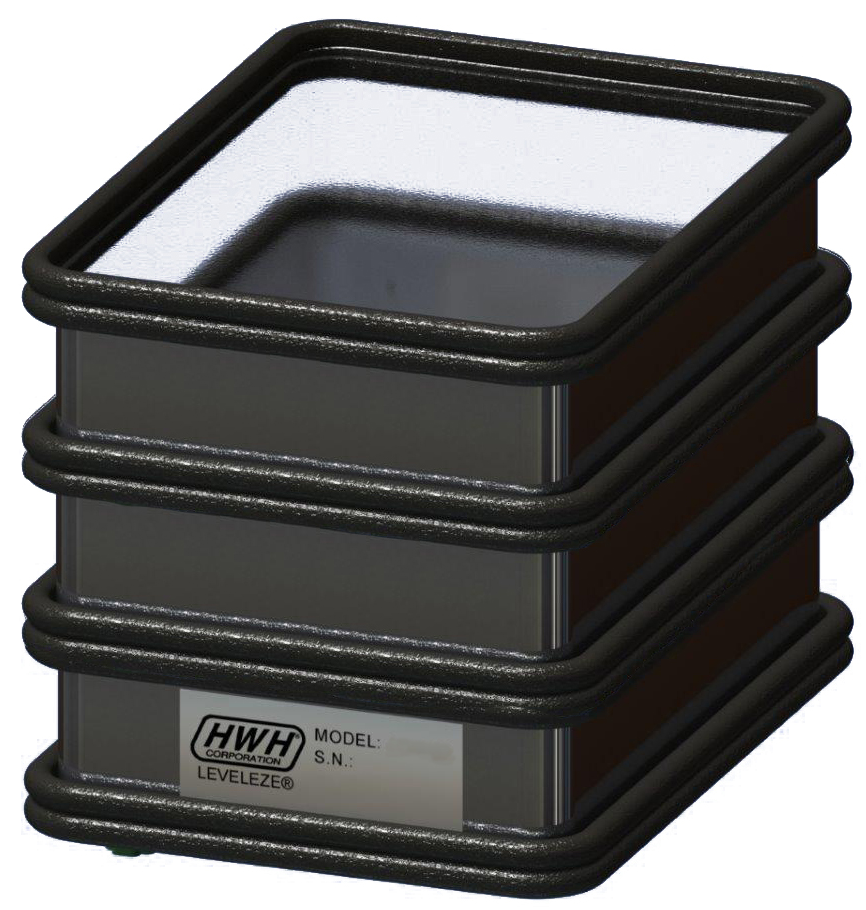
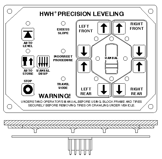
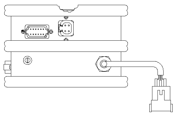
PRECISION LEVELING: 2010-Call for Information
Precision leveling is a special system which allows a vehicle, motorized or towable to be leveled within about 1/32″ of true level. Most of the components are specific to the precision leveling system and are not interchangeable with standard leveling system components. The manifold for the power unit is special. The jacks are double acting, fixed jacks with a special manifold and MIOM attached to each jack. The MIOMs are specific to the location of the jack, left front, right front, left rear and right rear. The system uses 3 level sensing units mounted to a special mounting/adjustment plate. One sensing unit is for the side to side leveling at the front, one for the side to side leveling at the rear and one does the front to rear leveling. The system does a “rough” leveling and stabilizing procedure then goes into the precision leveling mode to finish. All of the components are still available but you should contact HWH before ordering parts. None of the precision leveling system parts will work with a standard leveling system.
|
Touch Panel
|
Control Box
|
|
Level Sensing Unit
|
Power Unit Manifold
|
|
Jack Assembly With Valves
|
|
ACTIVE AIR: 2006-PRESENT
The Active Air system is a suspension control system. It was designed to enhance the drivability of the vehicle. The first systems were all aftermarket installed but eventually several coach manufacturers installed the system during the production of the vehicle. The system incorporated electronic height sensors, steering sensors and special air solenoid valve manifolds. Along with suspension control, the system provided air leveling and could control hydraulic leveling, room extensions and other equipment. The system did not use a touch panel; instead it used a LCD screen. The first screens were monochrome but the later screens were color. The Active Air system is the only HWH system to use the LCD screen. The system is very complicated and there are quite a few different LCD screen assemblies so it is very important to contact HWH when working on an Active Air system.
|
Monochrome LCD Assembly
|
Color LCD Assembly
|