1XX SERIES |
|
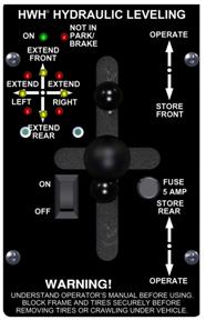
100 SERIES | ||||
PRODUCED: YYYY – YYYY | ||||
PRODUCED: YYYY – YYYY | ||||
| CONTROL PANEL | INDICATOR LIGHT PANEL | |||
 |
 |
 |
 |
 |
• 100 Series uses separate indicator light panel >>> |
Without HWH® Suspension Air Dump |
With HWH® Suspension Air Dump |
With Toggle Switch | |
With Rocker Switch | ||||
• Indicator lights are on a plate mounted SEPARATE from the control unit. | ||||
• Used with straight-acting or kick-down jacks. | ||||
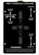
| 110 SERIES | |
PRODUCED: YYYY – YYYY | |
PRODUCED: YYYY – YYYY | |
PRODUCED: YYYY – YYYY | |
| CONTROL PANEL | |
 |
 |
Without HWH® Suspension Air Dump |
With HWH® Suspension Air Dump |
• Single lever control for each jack. | |
2XX SERIES |
| 200 SERIES | ||
PRODUCED: YYYY – YYYY | ||
| CONTROL PANEL | INDICATOR LIGHT PANEL | |
 |
 |
 |
• 200 Series uses separate indicator light panel >>> |
Without HWH® Suspension Air Dump |
With HWH® Suspension Air Dump |
• Indicator lights are on a plate mounted SEPARATE from the control unit. | ||
• Used with kick-down or straight-acting jacks. | ||
| 210/225 SERIES | |
PRODUCED: YYYY – YYYY | |
PRODUCED: YYYY – YYYY | |
| CONTROL PANEL |
• Single joystick control for all four jacks.
|
 | |
3XX SERIES |
| 300 SERIES |
PRODUCED: YYYY – YYYY |
| 305 SERIES |
PRODUCED: YYYY – YYYY |
| 310 SERIES – ROCKER-SWITCH |
PRODUCED: YYYY – YYYY |
| 310 SERIES – TOUCH PANEL | ||
PRODUCED 1995 – 2003 | ||
PRODUCED: YYYY – YYYY | ||
| CONTROL PANEL | CONTROL BOX | |
 |
 |
 |
• Without HWH® Suspension Air Dump |
• With HWH® Suspension Pilot Air Dump |
• Control Box is 2-3/4″ x 4-1/4″ x 7-1/2″ |
• Touch Panel | ||
| 325 SERIES | |||
PRODUCED: 2003 – PRESENT | |||
PRODUCED: 2003 – 2004 | |||
PRODUCED: YYYY – YYYY | |||
| “SHORT” PC BOARD SERIES | PRODUCED: 2003 – 2004 | |||
| CONTROL PANEL | CONTROL BOX | ||
FRONT |
BACK | ||
 |
 |
 | |
• Touch Panel |
• Touch panel has four connectors on back. |
• Short PC Board | |
| “LONG” PC BOARD SERIES | PRODUCED: 2003 – Present | |||
| CONTROL PANEL | CONTROL BOX | ||
FRONT |
BACK | ||
 |
 |
 |
 |
With |
Without HWH® Suspension Air Dump |
• Touch panel has one five-pin connector on back. |
• Long PC Board |
• Touch Panel | |||
4XX SERIES |
| 400 SERIES | |
PRODUCED: 1985 – 1992 | |
| CONTROL PANELS | |
 |
 |
NON BI-AXIS® |
BI-AXIS® |
• Control panel equipped with paddle switches. | |
5XX SERIES |
| 500 SERIES | ||
PRODUCED: 1988 – 1993 | ||
PRODUCED: YYYY – YYYY | ||
PRODUCED: YYYY – YYYY | ||
PRODUCED: YYYY – YYYY | ||
| CONTROL PANEL | CONTROL BOX | |
FRONT |
BACK | |
 |
 |
 |
• Touch Panel |
• Touch panel has a forty-pin connector on back. |
• Glass or blade style fuses may be found in a 500 Series control box. |
• Used for Air Leveling or combination Air/Hydraulic Leveling. | ||
| 510 SERIES (510M SERIES – AP8073) | ||
PRODUCED: 1990-1/2 – 1993 | ||
| CONTROL PANEL | CONTROL BOX | |
| FRONT | BACK | |
 |
 |
 |
• Touch Panel |
Touch panel has either |
Control box is 2-3/4″ x 4-1/4″ x 6-1/2″ |
• Connecting cable between the control box and touch panel was a | ||
6XX SERIES |
| 600 SERIES | ||
PRODUCED: 1988-1993 | ||
PRODUCED: YYYY – YYYY | ||
PRODUCED: YYYY – YYYY | ||
| CONTROL PANEL | CONTROL BOX | |
| FRONT | BACK | |
 |
 |
 |
• Touch Panel |
Touch panel has an eight-wire connector on back. |
• Only blade style fuses will be found in a 600 Series control box. |
• Connecting cable between the control box and the touch panel is 3/8″ wide, flat, eight-wire ribbon cable. | ||
| 610 SERIES | ||
PRODUCED: 1992 – 1993 | ||
PRODUCED: 1993 – 2003 | ||
| 610 SERIES – NON-CENTRAL GROUND PRODUCED: 1992-1993 | ||
| CONTROL PANEL | CONTROL BOX | |
| FRONT | BACK | |
 |
 |
 |
• Touch Panel |
Touch panel has an eight-wire connector on back. |
Control Box is 2-3/4″ x 4-1/2″ x 6-1/2″. |
• Connecting cable between the control box and touch panel is a 3/8″ wide, flat, eight-wire ribbon cable. | ||
| 610 SERIES – CENTRAL GROUND PRODUCED: 1993 – 2003 | ||
| CONTROL PANEL | CONTROL BOX | |
| FRONT | BACK | |
 |
 |
 |
• Touch Panel |
Touch panel has one eleven-pin connector on back. |
• Control Box is 2-3/4″ x 4-1/2″ x 7-1/2″. |
• Connecting cable between the control box and touch panel is an eleven-pin cable assembly. | ||
| 625 & 625S SERIES | ||
PRODUCED: 2003 – PRESENT | ||
PRODUCED: 2006 | ||
| 625 SERIES PRODUCED: 2003 – PRESENT | ||
| CONTROL PANEL | CONTROL BOX | |
| FRONT | BACK | |
 |
 |
 |
• Touch Panel |
Five-pin connector on back. |
• Control box has an 8″ x 11″ clear plastic cover. |
• The jack warning switch plugs are grey. | ||
| 625S (SINGLE STEP) SERIES PRODUCED: 2006 | ||
| CONTROL PANEL | CONTROL BOX | |
| FRONT | BACK | |
 |
 |
 |
• Touch Panel |
• Touch panel has a five-pin connector on back. |
• Control box has an 8″ x 11′ clear plastic cover. |
• Jack warning switch plugs are grey. | ||
| 680 SERIES | ||
PRODUCED: 1997 – 2002 | ||
PRODUCED: YYYY – YYYY | ||
PRODUCED: YYYY – YYYY | ||
| CONTROL PANEL | CONTROL BOX | |
| FRONT | BACK | |
 |
 |
 |
• Touch Panel |
Touch panel has an eight-wire connector on back. |
• Control box is 3-1/2″ x 14-1/2″ x 19″. |
• Used for Air Leveling or combination Air/Hydraulic Leveling | ||
7XX SERIES |
| 700 SERIES | ||
PRODUCED: YYYY – PRESENT | ||
| CONTROL PANEL | SENSING UNIT & I/O CONTROL MODULE (NO CONTROL BOX) | |
| FRONT | BACK | |
 |
 |
|
• Touch Panel |
• Touch panel has a five-pin connector on back. |
• MIOM located at each air manifold. |
• Use for Air Leveling | ||
| 725 SERIES | ||
PRODUCED: YYYY – PRESENT | ||
PRODUCED: YYYY – YYYY | ||
PRODUCED: YYYY – YYYY | ||
| CONTROL PANEL | SENSING UNIT & I/O CONTROL MODULE (NO CONTROL BOX) | |
| FRONT | BACK | |
 |
 |
|
• Touch Panel |
• Touch panel has a five-pin connector on back. |
• MIOM mounted on pump. |
• All 725 Series are Single-Step, unless they have kick-down jacks. | ||
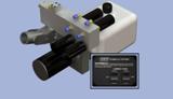
2000 SERIES |


HAND-PUMP |
| 2-POINT LANDING GEAR |
PRODUCED: YYYY – YYYY |
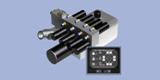
| 4-POINT LEVELING / LANDING GEAR |
PRODUCED: YYYY – YYYY |
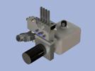
| 4-POINT LEVELING / LANDING GEAR |
PRODUCED: YYYY – YYYY |
| 4-POINT LEVELING / LANDING GEAR |
PRODUCED: YYYY – YYYY |
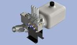
| EMERGENCY JACK SYSTEM |
PRODUCED: YYYY – YYYY (Operator Manual# ML46130) |
ACTIVE AIR SUSPENSION |
| ACTIVE AIR SUSPENSION | ||
HWH® Active Air Suspension & Computer-Controlled Air Leveling System | ||
| CONTROL PANELS | CONTROL MODULE & SENSING UNIT | |
PICTURE |
PICTURE |
PICTURE |