| ||
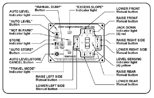
| Travel Mode light is on. | Travel Model light is off. Continue to test without JACK DOWN indicator light checks. Disregard JACK DOWN indicator light checks in STEP 4 test procedures. | |
JACK DOWN LIGHT DOES NOT TURN ON
| ||
| JACK DOWN light is now on. | JACK DOWN light is still off. | |
JACK DOWN LIGHT DOES NOT TURN ON
| ||||||||
| Continue LR jack testing | Continue LF jack testing | Continue RF jack testing | Continue RR jack testing | |||||
JACK DOWN LIGHT DOES NOT TURN ON
|
NOTE: ALL POWER SHOULD BE REMOVED FROM HWH LEVELING SYSTEM WHEN CHECKING RESISTANCE. When measuring hollow pin in harness connector do not insert probe into pin or damage could occur. Insert a wire of smaller diameter of pin (i.e. paper clip).
| ||
| Warning light now comes on: There is a problem with the white ground wire in the harness. Check terminal at Packard connector for good crimp/terminal. If bad repair crimp/terminal and retest. If light still comes on, repair/replace harness. |
Warning light still does not come on. | |
JACK DOWN LIGHT DOES NOT TURN ON
|
NOTE: ALL POWER SHOULD BE REMOVED FROM HWH LEVELING SYSTEM WHEN CHECKING RESISTANCE. When measuring hollow pin in harness connector do not insert probe into pin or damage could occur. Insert a wire of smaller diameter of pin (i.e. paper clip).
| ||
| If there is no continuity, there is a problem with the warning switch wire or ground wire from the 11 pin. | There is good continuity between the two pins. | |
JACK DOWN LIGHT DOES NOT TURN ON
|
NOTE: ALL POWER SHOULD BE REMOVED FROM HWH LEVELING SYSTEM WHEN CHECKING RESISTANCE. When measuring hollow pin in harness connector do not insert probe into pin or damage could occur. Insert a wire of smaller diameter of pin (i.e. paper clip).
| ||
| If there is a difference in the voltage greater than 1 volt, the I/O module needs to be replaced. | If the voltage is good, the problem is the I/O module or touch panel. Replace the touch panel first. If the problem remains, reinstall the original touch panel and replace the I/O module. | |

