|
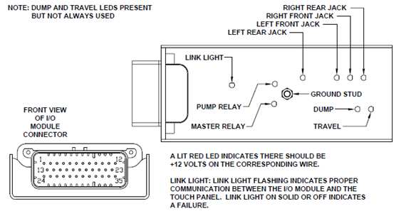
NOTE: ALL POWER SHOULD BE REMOVED FROM HWH LEVELING SYSTEM WHEN CHECKING RESISTANCE. When measuring hollow pin in harness connector do not insert probe into pin or damage could occur. Insert a wire of smaller diameter of pin (i.e. paper clip). Unplug the 35 pin connector at the I/O module. Check for continuity between the signal wire for the warning switch and the ground wire for the warning switches on pin 11. If there is continuity, the wires are shorted and need to be repaired. If there is no continuity between the warning switch signal wire and the ground wire on pin 11, check for continuity between the warning switch signal wire and chassis ground. If there is continuity to ground, the warning switch signal wire is shorted to ground and must be repaired. If there is no continuity to ground, check and record the voltage between pin 35 of the 35 pin harness connector and the brass ground stud on the top of the I/O module. Plug the 35 pin connector back in. Check the voltage between the ground and signal wire in the warning switch plug. The voltage should be within less than 1 volt of the voltage you recorded on pin 35 of the harness connector. If the voltage is good, replace the touch panel. If there is a difference in the voltage greater than 1 volt, the I/O module needs to be replaced.
| |
| Problem resolved indicator light is off | |
JACK DOWN INDICATOR LIGHT STAYED ON WITH WARNING SWITCH UNPLUGGED

