- CHAPTER 1 Introduction
- CHAPTER 2 400 Series, Paddle Switch-Controlled – NON-BI-AXIS®
- CHAPTER 3 400 Series, Paddle Switch-Controlled – BI-AXIS®
- CHAPTER 4 500 Series, Touch Panel/Computer-Controlled – BI-AXIS®
- CHAPTER 5 510 Series, Touch Panel/Computer-Controlled – BI-AXIS®
- CHAPTER 6 600 Series, Touch Panel/Computer-Controlled – BI-AXIS®
- CHAPTER 7 610 Series, Touch Panel/Computer-Controlled – BI-AXIS®
- CHAPTER 8 610 CG Series, Touch Panel/Computer-Controlled “Central Ground (CG)” – BI-AXIS®
- CONCLUSION
- TEST
LESSON 13 – PART 2, deals with identifying the different early HWH® computerized, automatic hydraulic leveling systems and the basic operation of each system. To properly diagnose problems or obtain parts for repairs, you not only have to be able to identify which system you are working on, you also have to know how that system should function. For example, a 510 Series system with kick-down jacks functions differently than a 610 Series system with kick-down jacks. Although all automatic leveling systems up to and including the 625S Series Single-Step leveling system used jacks with single-acting cylinders, some present day automatic computerized leveling systems will use jacks with a double-acting cylinder.
There are two basic types of leveling systems, the “manual” systems and the “automatic computerized” systems. The “manual” systems are covered in LESSON 13 – PART 1. With “automatic computerized” systems, all functions of the leveling procedure, including air dump, are controlled by a computer that is part of the system. Store functions, like manual touch panel systems, are automatic. Automatic systems also have manual capability for operator control.
Control panels, control boxes, valves, and other system features will be used in the identification of the systems. Due to the visual similarity of touch panels and control boxes, it is important to understand less obvious differences. Several touch panels are actually used with two different Series control boxes. The differences may be (but not limited to) the style of touch panel cable, valve arrangements on the hydraulic manifolds or even the type of warning switch used.
Most of the computerized hydraulic leveling systems have a repair manual available but it is necessary to identify the system to obtain the correct manual. For example, there are two completely different 610 Series leveling systems. Each has its own repair manual. Much of the diagnostics for each system is not interchangeable. Using the wrong manual will probably result in an incorrect diagnosis of the issue.
IMPORTANT: It would be very helpful to study LESSON 8 (Hydraulics and HWH®) and LESSON 9 (Electronics and HWH®) before continuing with this lesson or working on HWH® equipment. These two lessons identify the individual system components along with their function and some diagnostics. This lesson will deal with some component information but not in great detail. As you study this lesson, refer back to LESSON 8 and LESSON 9 to get greater detailed information about specific components.
If you want to review a specific system, return to the lesson directory and click on the system you wish to review. This lesson only covers systems for motorized vehicles.
Note: For most systems (not all) there are complete schematics, diagrams and/or comprehensive repair manuals on the HWH® web site at www.hwh.com. These will be located under “Tech Support, Manuals, Online Schools”.
The 400 Series paddle switch system was the first computerized, automatic leveling system developed by HWH®. The paddle switch systems are easily recognized by the control panel. The panel incorporates a Series of flat toggle type switches or “paddle switches”.
|

Figure 1
Not only does the panel have the control switches, it also contains the computer chip, control outputs and information inputs. There is no separate ‘control panel” and “control box”. The control outputs would be for the solenoid valves, the relays on the pump, a master warning light control and air dump control when so equipped. The information inputs would be the jack down warning switches, the level sensing unit and the hydraulic manifold pressure switch. There were quite a few different control panels. There were panels for straight-acting or kick-down style jacks. A different control panel was needed if air dump was used. There were different programs that may have extended one or two jacks when automatically leveling. There were even panels where the only difference was the color of the panel lexan; there were gray, black, brown, and silver lexans.
The standard 400 Series panel was like the 100/110 Series lever controlled leveling systems. The panel was designed to control individual jacks. Even in the automatic mode, with a few exceptions, these systems operated individual jacks while leveling the vehicle. There is a BI-AXIS® 400 Series leveling system. This system will be discussed in the next chapter of this lesson. The BI-AXIS® panel has different text above the yellow paddle switch lens. Instead of “LEFT REAR – LEFT FRONT – RIGHT FRONT – RIGHT REAR” that is on the standard panels (Figure 1), a BI-AXIS® panel has “LEFT SIDE – FRONT – RIGHT SIDE – REAR” above the yellow lens. (CHAPTER 2, Figure 6) The BI-AXIS® hydraulic manifold is also totally different than the hydraulic manifold used with the standard 400 Series paddle switch systems.
Many of the 400 Series panels have been obsoleted. ML11428QR 004 is a quick reference sheet that lists all the 400 Series panels that have been available along with a panel that can be used to replace the existing panel if it has been obsoleted. The replacement panel may have a different color lexan and have a slightly different leveling program. This sheet is available on the HWH® web site.
At this time, the 400 Series systems can still be serviced with new, remanufactured or repaired parts. It may be possible in the future that due to availability of certain components, HWH® will not be able to supply the parts necessary to repair the system. The system may have to be replaced with a system available at that time. Depending on what systems are available, it may be possible some of the existing components such as the jacks, hoses, and pump can be used with a newer control system.
The 400 Series systems (including the BI-AXIS® systems) are unlike all of our other computerized systems. All other computerized systems have a touch panel and a control box or I/O module. The 400 switch system only has the paddle switch control panel. All inputs from the warning switches, manifold pressure switch, and the level sensing unit are routed to the paddle switch panel. All of these input signals are switched grounds from the component. Ignition power goes directly to the panel. Like other systems, it was recommended to use the ACC. side of the ignition switch. The ignition/ACC. wire is in a two pin plug with the ground wire for the panel. The ignition and ground wire are twisted together to reduce “noise” on the power wire. Control output signals for the solenoid valves, the relays, the master warning light and air dump (if so equipped), come directly from the paddle switch panel.
Most paddle switch panels had either six or seven switches and a five amp glass fuse. There is an ON/OFF switch, an AUTOMATIC LEVEL/AUTOMATIC RETRACT switch, a HORIZONTAL/VERTICAL switch (if the system was equipped with kick-down style jacks), and four individual jack switches for manual control of the jacks. The indicator lights for the panel are part of the paddle switches. Each switch can have two lights. The switches have a removable lens on each side of the switch. The indicator light bulbs are located beneath the lens and are replaceable. There is a small metal tab under the lens that when pulled up, pops the bulb out for replacement. There were different colored lens used. A red lens was used on each side of the ON/OFF switch, AUTO LEVEL/RETRACT switch and the HORIZONTAL/ VERTICAL switch, when present. On some panels, the lower lens on the ON/OFF switch was a red lens with “LOW VOLTS” printed on it. The manual jack control switches had yellow lens on the top side of the switch for the level indicator lights and a red lens on the bottom of the switch was the jack down indicator light. Some Blue Bird® panels had a black lens on the lower side of the jack control switches due to the fact Blue Bird® supplied their own jack down indicator lights.
|

Figure 2
Most of the paddle switches were three position ON/OFF/ON momentary switches. Some panels had a two position ON/OFF maintain switch. Panels that had the two position ON/OFF switch did not have an automatic off feature. The ON/OFF switch was pushed to the ON position to operate the system and had to be pushed to OFF, or EMERGENCY OFF on some panels, to turn the system off. Panels that have an automatic off feature used the three position (ON/OFF/ON) switch for the ON/OFF switch. Some systems were equipped with a remote panel that had the ON/OFF switch and the AUTOMATIC LEVEL / AUTOMATIC RETRACT switch. The main paddle switch panel for these systems did not have the ON/OFF switch or the AUTOMATIC LEVEL/AUTOMATIC RETRACT switch.
Because of the design of the paddle switch control panel, the panel switches a ground to control the pump relay, the hydraulic manifold solenoid valves and the air dump valves if so equipped. In the automatic mode, because these ground signals come from a small driver chip controlled by the processor, the ground signal is very weak. A transistor is needed for each component controlled by the paddle switch panel. There is a transistor for the pump relay mounted on a breaker/fuse panel mounted to the hydraulic manifold. That same panel will have a transistor for the air dump valves if an air dump system is used. |
Figure 3 |

Each solenoid valve on the manifold has a transistor mounted to the exterior of the valve. All of these transistors supply a ground to their components when the control panel grounds the transistor. Proper grounding of the hydraulic manifold is critical to the operation of the system. If the manifold has a weak ground due to loose mounting bolts, corrosion, or other issues, the component transistors will burn out. A transistor can become totally inoperative, the component will not function at all, or can become shorted to ground and the component will be on whenever the master relay is on. A valve can be open or the pump can run whenever the panel is on. Even if the manifold has a good ground, corrosion or loose mounting bolts can cause an issue with the transistors on the breaker/fuse panel mounted to the manifold. Again, the manifold and the breaker/fuse panel with transistors mounted to the manifold require good, clean and tight mounting connections to ensure proper system operation.
The breaker/fuse panel supplies power for the solenoid valves along with having the pump and air dump transistors. Originally, the panel was equipped with three automatic circuit breakers. An automatic circuit breaker will reset on its own after a cooling period. Some very early panels only had two breakers. Later, the breakers were replaced with three 20 amp inline automotive blade fuses. Each breaker or fuse supplies power to two solenoid valves. Newer panels are equipped with a panel ground wire to help insure a good ground for the panel.
A huge difference between all manually controlled leveling systems and the computerized automatic leveling systems is the relay arrangement for the pumps. The manual systems all have one relay to control the pump. (Some manual systems used two pump relays if the vehicle was equipped with an HWH® room extension.) All automatic leveling systems have two relays for the pump. There is a “master” relay and a “pump” relay. (Like with manual systems, there are different relay arrangements but all automatic leveling systems have at least one master and one pump relay.) The master relay is used to control power to operate the pump motor and the hydraulic manifold solenoid valves. The master relay is controlled with a +12 volt signal from the control panel when the control panel is on. The pump relay is controlled with a ground signal from the control panel through a transistor on the breaker/fuse panel. The +12 voltage for the pump relay coil is supplied from the switched side of the master relay. The master relay must be on for the pump to run. Both the master and pump relays used with the 400 systems were continuous duty relays with the same part number. The same relay used on the 400 systems is still available from HWH® today. An intermittent duty relay, like those used on present day systems, can be used for the pump relay, but will create some minor mounting and wiring problems.
Note: Detailed wiring diagrams for the 400 Series system are available in the repair manual for this system. The manual number is ML7879 and can be found on the HWH® web site under “Service Manuals” in the “Technical and Installation Information” section of the web site.
As with all leveling systems, the 400 Series jack down warning switches, the manifold pressure switch and the level sensing unit all provide a switched ground to the control panel. Due to the early technology used, the manifold pressure switch and the level sensing unit were connected to the control panel with a shielded cable to reduce electronic interference or “noise” that could inhibit operation of the system. There are small wires for the shielding cable that need to be grounded at the sensing unit and the manifold pressure switch.
Sensing units for the 400 Series systems used a five wire harness plus the shield wire that is grounded at the sensing unit. One of the five wires is a ground for the sensing unit. The other four wires were the signal wires. Each wire controls one yellow level light. The sensing unit is mounted in an “X” position to read the corners of the vehicle. The sensing unit also has an “UP” position. The sensing units have a sticker that indicates the proper mounting direction and the UP side of the sensing unit. There are three mounting screws with a spring between the sensing unit and mounting surface at each screw. The mounting screws are also the adjusting screws. The original sensing units have mercury bulbs as part of the assembly and are not available any more. A new style electronic sensing unit can be used to replace the original sensing unit but will need an adaptor harness kit so it will function properly. Contact HWH® technical service for assistance. |
Figure 4 |

The jack down warning switches used with the 400 Series systems switch a ground to control the red jack down warning lights on the control panel. Warning switches used with straight-acting jacks were different than switches used today. The older straight-acting jacks used a side port switch or a two inch plunder switch mounted on the top of the jack. Straight-acting jacks would extend approximately two inches before turning on the warning lights. These older switches were one wire switches and were grounded through the jack itself. A rusted pivot point on these jacks could cause a warning light to not come on. The kick-down jack warning switches were basically the same as used today. The main difference was the switch was grounded at the jack mounting bracket so the warning switch harnesses only had one wire per jack. Refer to SECTION 2-8 in LESSON 9, “Electronics and HWH®” for detailed views and explanations for the warning switches used with the 400 systems. The 400 Series system is the only automatic system where the jack down warning switches are not used for any part of system operation except the panel red warning lights. A warning switch that will not turn on or off will not interfere with any automatic leveling or store function.
The only thing that is similar between present day leveling systems and the 400 Series non-BI-AXIS® leveling system is the use of single-acting cylinders for the jacks. The manifold and pump are mounted separately and can be in different locations. The manifold and pump are connected with a pressure line to deliver fluid to the manifold and a low pressure line for fluid return to the pump.
The manifold uses six solenoid valves if kick-down style jacks are used and five solenoid valves if straight-acting jacks are used. The manifold also uses a shuttle valve, an individual check valve for each jack, an adjustable pressure reducing valve, a pressure switch and if kick-down jacks are used, a relief “bleed” valve for thermal expansion.
Review CHAPTER 4 of LESSON 8, “Hydraulics and HWH®” for detailed explanations of the different hydraulic components such as shuttle valves and actuators.
Note: Detailed hydraulic plumbing diagrams for the 400 Series system are available in the repair manual for this system. The manual number is ML7879 and can be found on the HWH® web site under “Service Manuals” in the “Technical and Installation Information” section of the web site.
All 400 Series manifolds have one solenoid valve for each jack. The manifolds also will have a “stabilize” valve. If the system has kick-down jacks, the manifold will be equipped with a “horizontal/vertical” valve. All of the solenoid valves on the manifold are the same and are interchangeable. The valves are normally closed, zero leak valves. The jack valves open to extend and retract the jack cylinders. The stabilize valve opens during automatic leveling to stabilize the vehicle after leveling is complete. The adjustable relief valve lowers the pump pressure during the stabilize procedure. The four individual jack check valves allow low pressure fluid to flow to jacks that need to extend during the stabilize procedure while keeping jacks already under a higher pressure in their present position. The horizontal/vertical valve opens to move jacks to the vertical or horizontal position. The bleed valve is not shown in Figure 5. The shuttle valve and the relief valve must be removed to access the bleed valve. |
Figure 5 |

The bleed valve relieves pressure between the jack kick down actuators and the manifold caused by thermal expansion so jacks will not kick down to a vertical position while the vehicle is traveling. The shuttle valve blocks the return line to the pump when the pump is running. The pressure switch is used to indicate an “excess slope” situation. Most 400 Series systems use a 3000 psi pressure switch although some early systems used a 2500 psi pressure switch.
Systems with kick-down style jacks have two hydraulic hoses routed from the manifold to each jack. One hose is for the kick down actuator cylinder and the other hose is for the main jack cylinder. The hose for the actuator is a common hose teed to each jack actuator. There is only one connection at the manifold for all four jack actuators. There is an individual connection at the manifold for each jack cylinder.
Manual leveling: The ignition key must be on and the park brake should be set. The 400 Series systems do not use a park brake signal to inhibit system operation. If the system uses kick-down jacks, the front of the vehicle should be the low end. Lifting the weight of the vehicle off of the rear wheels will allow the vehicle to roll off of kick-down jacks.
Note: If the vehicle is equipped with an air suspension, air should be dumped before a leveling procedure is started. If the vehicle has kick-down jacks, the air should be dumped after the jacks are in the vertical position.
Push the ON/OFF paddle switch to the on position. The red system on light should come on. The panel will send a +12 volt signal to turn the master relay on. The master relay supplies power to the breaker/ fuse panel for the solenoid valves and to the pump relay.
If the system has kick-down jacks, push and hold the “Horizontal/Vertical” paddle switch to the “Vertical” position. The panel will send a ground signal to the breaker/fuse panel pump transistor. The pump transistor sends a ground signal to the pump relay. The pump relay contacts will close and send +12 volts to the pump motor. The panel, at the same time, sends ground signal to the “Horizontal/Vertical” valve. With the pump running and the valve open, pressure forces the jack actuators to push the jacks to the vertical position. When all four red jack down warning lights are on, release the “Horizontal/Vertical” paddle switch.
If the system has straight-acting jacks or when the jacks are in the vertical position, the jacks can be extended to level the vehicle by pushing individual jack control paddle switches to the “Extend” position. Pushing a switch to the “Extend” position sends a ground signal to the pump transistor on the breaker/fuse panel and the appropriate jack solenoid valve. The pump will push oil to that jack and the jack will extend until the switch is released.
The system level sensing unit will send a ground signal to the panel to turn on a yellow level light. A lit level light indicates a corner of the vehicle is low. One or two level lights can be on at the same time. Opposing level lights such as the right front and the left rear should not be on. Push and hold the appropriate jack control paddle switches until the yellow lights are all out. Push and hold the paddle switch or switches for jacks not used to level the vehicle. These jacks should be extended until they lift the vehicle slightly, approximately ½ inch.
Manual retract: The ignition must be in the ON or ACC. position to use the manual control paddle switches to retract the jacks.
Push the ON/OFF paddle switch to the on position. The red system on light should come on. The panel will send a +12 volt signal to turn the master relay on. The master relay supplies power to the breaker/ fuse panel for the solenoid valves.
Push and hold the manual jack control paddle switches to “RETRACT”. This sends a ground signal to open the solenoid valves and allows the fluid to return to the pump from the jacks.
If the system has straight-acting jacks, hold the paddle switches to “RETRACT” until the red jack down warning lights are out. Remember, the red warning light goes out with the foot of the jack still extended one to two inches. Hold the paddle switches to “RETRACT” for five to ten seconds after the red warning lights go out. This will help make sure the foot of the jack is fully retracted.
If the system has kick-down jacks, the foot of the jack must be off the ground before the jack can return to the vertical position. It will be necessary to visually check that the jacks are retracted far enough to swing the jacks to the vertical position. When all jacks will clear the ground, push and hold the “HORIZONTAL/VERTICAL” paddle switch to “VERTICAL” until all red jack down warning lights are out. Use the individual jack control switches to make sure the foot of each jack is fully retracted.
Note: It may be best to retract the front jacks together and then the rear jacks together. This can help reduce twisting of the vehicle while retracting the jacks.
Automatic leveling: The ignition key must be on and the park brake should be set. The 400 Series systems do not use a park brake signal to inhibit system operation. If the system uses kick-down jacks, the front of the vehicle should be the low end. Lifting the weight of the vehicle off of the rear wheels will allow the vehicle to roll off of kick-down jacks.
Note: If the vehicle has an air suspension but is not equipped with an HWH® air dump system. The suspension air should be dumped using an air dump system supplied by the coach manufacturer. If the vehicle has straight-acting jacks, dump the air before starting the leveling procedure. If the vehicle has kick-down jacks, dump the air after the jacks are put in the vertical position but before starting the leveling procedure.
Push the ON/OFF paddle switch to the on position. The red system on light should come on. The panel will send a +12 volt signal to turn the master relay on. The master relay supplies power to the breaker/ fuse panel for the solenoid valves and to the pump relay.
If the vehicle has kick-down jacks, Push the “AUTOMATIC LEVELING/RETRACT” switch to “AUTOMATIC LEVELING” The red Automatic Leveling light will start to flash. The panel will send ground signals to the pump transistor on the breaker/fuse panel and to the horizontal/vertical valve. The pump will push fluid through the horizontal/vertical valve to all four jack actuators at the same time. The jacks will swing to the vertical position. There is no set order that the jacks go vertical. As a jack swings vertical, the jack warning switch sends a ground to the control panel to turn the appropriate red warning light on. When the control panel sees a ground from the 3000 psi manifold pressure switch, the panel will turn the pump and the horizontal/vertical valve off. The red Automatic Leveling light will stop flashing and remain on steady.
Push the “AUTOMATIC LEVELING/RETRACT” switch to “AUTOMATIC LEVELING” a second time. The red Automatic Leveling light will start flashing. If the vehicle is equipped with an HWH® air dump system, the air will dump from the suspension at this time. Depending on the program, the system will dump air for approximately 30 seconds. (If the system does not have an air dump system, the leveling procedure will start when the switch is pushed to “AUTOMATIC LEVELING”.) The system will start to level the vehicle according to lit yellow level lights. Different panels have different leveling programs. Normally, the system will extend jacks to turn lit rear lights off first. Some systems will operate two jacks at the same time, depending on lit level lights. When all four yellow level lights are out, the system will pause briefly then automatically go into the stabilize procedure.
The stabilize procedure is a timed sequence. That means the pump will run for a specific amount of time then shut off. There are different times for different systems. The stabilize procedure will be 20 seconds for a vehicle without an HWH® air dump system, ten seconds for a vehicle with an HWH® air dump system and 60 seconds for a Blue Bird® motor home with straight-acting jacks. During the stabilize procedure, the panel will send a ground signal to the pump transistor on the breaker/fuse panel and to the stabilize valve. Individual jack valves DO NOT open. When the stabilize valve is open, fluid is directed through the stabilize valve, then through the individual jack check valves out to the jacks that need to be extended. Fluid is also directed to a pressure reducing valve. This lowers the pressure available to extend jacks to approximately 250 to 350 psi. Jacks on the ground under pressure, will not extend. The check valves keep the jacks under pressure from retracting. Jacks not under pressure will extend until the system pressure allowed by the pressure reducing valve is reached. When the stabilize timer is done, the red Automatic Leveling light will shut off and the red System On light will turn off. Systems with the two position ON/OFF switch will remain on until the switch is turned off.
If the vehicle has straight-acting jacks, review the automatic leveling sequence for kick-down jacks starting with “Push the “AUTOMATIC LEVELING/RETRACT” switch to “AUTOMATIC LEVELING” a second time. At this point, the procedure is the same for both systems.
Automatic retract: The ignition key must be on and the park brake should be set. The 400 Series systems do not use a park brake signal to inhibit system operation.
Note: If the vehicle has an air suspension, it is best to start the vehicle engine at this time to build up air pressure.
Push the ON/OFF paddle switch to the on position. The red system on light should come on. The panel will send a +12 volt signal to turn the master relay on. The master relay supplies power to the breaker/ fuse panel for the solenoid valves and to the pump relay.
Push the “AUTOMATIC LEVELING/RETRACT” switch to “AUTOMATIC RETRACT”. The red Automatic Retract light will start to flash. The pump DOES NOT run during the retract procedure. The control panel will send a ground signal to all of the individual jack solenoid valves. The panel will also send a ground signal to the horizontal/vertical valve if the system is equipped with kick-down jacks. The jack springs will retract the cylinders, forcing the fluid back to the pump. If the vehicle is equipped with kick-down jacks, the springs will pull the jacks to the horizontal position as the foot of the jack clears the ground. If the system has straight-acting jacks, the jack warning switch contacts will open when the jack is within one to two inches of being fully retracted. The red jack down warning light will go out. If the system has kick-down jacks, the jack down warning switch contacts will open after the jack swings back to the horizontal position. The red jack down warning light will go out. The 400 Series systems have a timed automatic retract procedure. The procedure time is four minutes from when the “AUTOMATIC LEVELING/RETRACT” switch is pushed to “AUTOMATIC RETRACT”. At the end of the four minute time, the red Automatic Retract light will go out and the red System On light will go out. Systems with the two position ON/OFF switch will remain on until the switch is turned off.
Additional information for the 400 Series systems
- Excess Slope: Excess slope is when one or two jacks become fully extended with their yellow level lights remaining on. There is no indicator light for excess slope. When a jack becomes fully extended and its level light stays on, the pressure in the system will build up until the 3000 psi manifold pressure switch turns on. This sends a ground signal to the control panel. The processor will immediately turn the pump and any open jack solenoid valves off. After a several second delay, the system will go to the stabilize procedure and turn off after completing the stabilize procedure.
- Low Volts: Some paddle switch panels are equipped with a red “LOW VOLTS” lens on the bottom of the “ON/OFF” paddle switch. This light will come on if the voltage on the red and white twisted pair of wires going to the panel drops below approximately 8.5 volts. The system may continue to function but should be turned off if the LOW VOLTS light turns on. Low voltage can damage some of the system components.
- Master warning light: Most vehicles will have a master “JACKS DOWN” warning light that will be on anytime one or more individual paddle switch panel red jack down warning lights are on. The master warning light is controlled with a switched ground from the paddle switch panel. Power for the light is usually supplied by the paddle switch panel.
The 400 Series Paddle Switch-Control BI-AXIS® system was used mainly on the larger Holiday Rambler® motor homes that were equipped with an air suspension. There were other coaches that used this system. The standard paddle switch system panel and the BI-AXIS® paddle switch system panel are very similar except for the wording around the manual jack control switches. Refer to CHAPTER 2, Figure 1 or Figure 2 for a view of the standard paddle switch panel. Figure 6 below shows the BI-AXIS® panels.
|

Figure 6
Review CHAPTER 2 for a detailed discussion of the 400 Series systems. Because the components of both systems are very much alike, the same in most cases, and the two systems are operationally much the same, only the differences in the two systems will be discussed in this chapter.
There are virtually no differences in the two systems electrically. The control panel for both systems is wired the same. The only difference in the two panels besides the visible difference of the panel lexan, is the individual jack control switches operate two jacks at the same time instead of one at a time. All of the system components, except the level sensing unit, such as valves, warning switches, pressure switch, master and pump relays, the breaker/fuse panel and the pump work the same for both systems. The repair part numbers for the individual parts are the same. One small difference is the breaker/fuse panel does not mount to the hydraulic manifold as it does on a standard 400 Series manifold. It is mounted separate from the manifold but must be mounted very close to the manifold mounting location. The grounding requirements for all of the components are the same. Like the standard 400 system, proper grounding of components is critical for the proper operation and maintenance of the 400 Series BI-AXIS® systems.
Level sensing unit: The level sensing unit for a 400 Series BI-AXIS® system is electrically the same as a standard 400 Series level sensing unit. Like the standard system, the sensing unit switches a ground to turn the control panel yellow level lights on. BUT, it is mounted with a different orientation. The BI-AXIS® sensing unit mounting sticker looks the same but the switches in the sensing unit are now orientated to indicate the front, rear, left side or right side low instead of corners of the vehicle. Like the standard 400 system sensing unit, the BI-AXIS® sensing unit has a shielding cable that is grounded at the sensing unit. |
Figure 7 |

The 400 Series BI-AXIS® leveling system incorporates the same style leveling jacks and hydraulic pump that the standard 400 Series system uses except the BI-AXIS® system was only available with kick-down style jacks. Although the same valve functions were used on the BI-AXIS® hydraulic manifold, the manifold arrangement was totally different.
Like the standard manifold the BI-AXIS® manifold had a shuttle valve to isolate the pressure side of the manifold from the return side, 4 jack solenoid valves; one valve for each jack, a horizontal/vertical valve for the kick-down procedure, a bleed valve to keep the jacks in the horizontal position while traveling, a stabilize valve and a pressure reducing valve for stabilizing the vehicle after the leveling procedure was complete. The manifold also has a 3000 psi pressure switch for the kick-down procedure and for the indication of excess slope. The four jack valves, the horizontal/vertical valve, and the stabilize valve are all the same part number valve and are interchangeable with each other and also with the valves on a standard 400 Series system. Although they perform the same function for both systems, the shuttle valve and the bleed valve are different from the standard system valves and are not interchangeable. The pressure reducing valve and the 3000 psi pressure switch are the same for both systems. The biggest difference between the two styles of hydraulic manifolds is the check valve arrangement. The standard 400 Series manifold had one check valve for each jack and was only used for stabilizing the vehicle. The BI-AXIS® hydraulic manifold had 2 check valves for each jack, an inner check valve and an outer check valve. |
Figure 8 |

The check valve arrangements in the BI-AXIS® manifold are necessary for the leveling procedure and the stabilizing procedure. During leveling, two valves may be opened at the same time. During the stabilizing procedure, all four jack solenoid valves are open. The check valve arrangements prevent higher pressure fluid flowing from a jack that is extended to a jack that is not extended. This keeps the vehicle from dropping during a leveling or stabilizing procedure. The outer check valve can be accessed simply by removing the check valve cap. The inner check valve is directly below the outer check valve but is on the other side of the solenoid valve seat. The solenoid valve must be removed to access the inner check valve. Except for the pressure connection from the pump, the hose connections are not shown in Figure 8 and are on the back side of the manifold. There are two hydraulic hoses for each jack, one for the kick-down actuator and one for the main jack cylinder. All four jack actuator hoses tee together and are routed to one fitting on the manifold. Each hose for the main jack cylinders has its own fitting on the manifold.
The schematics in Figure 9 and Figure 10 on the following page are for the 400 Series standard and BI-AXIS® systems. These schematics show how the two systems differ hydraulically.
Figure 9 to the right shows a 400 Series standard manifold. Notice the four check valves are on a different circuit than the jack solenoid valves. If everything is working correctly, the only time the check valves are relevant, is when the system is in the stabilize mode. A diagnostic difference between the 400 standard system and not only the 400 Series BI-AXIS® system but all BI-AXIS® automatic hydraulic leveling systems is when a jack will not stay extended. With the standard system, a solenoid valve or check valve with an internal leak would cause a jack to retract when the system is inactive. With a BI-AXIS® system, only a solenoid valve with an internal leak would cause this problem. A check valve that is leaking would not allow a jack to retract when the solenoid valve is closed. |
Figure 9 |

Figure 10 shows the 400 Series BI-AXIS® manifold. Note the difference in the check valve arrangements between the two manifolds. The BI-AXIS® manifold has two check valves for each solenoid valve. The check valves are on the same hydraulic circuit as the jack solenoid valves and are in the circuit before the solenoid valves. This schematic shows that, other than visible oil leaks, only a solenoid valve with an internal leak will cause a jack to retract when the system is inactive. The hydraulic circuits for the horizontal/vertical valve along with the bleed valve and the stabilize valve with the pressure reducing valve are virtually the same for both systems. The only difference in those circuits is the standard bleed valve is internally mounted and the BI-AXIS® bleed valve is externally mounted. |
Figure 10 |

Review SECTION 2-3 and SECTION 2-4 of CHAPTER 2 in this lesson for complete operating information about the 400 Series BI-AXIS® leveling system. The only difference between the standard 400 Series system and the BI-AXIS® 400 Series system is the operation of two jacks at a time for leveling. Putting kick-down jacks in the vertical position, manual or automatic, is the same for both systems, air dump procedures are the same for both systems, excess slope is the same for both systems except the BI-AXIS® system will almost always have at least two jacks fully extended to go into an excess slope situation, and all electrical functions such as jack down warning switches, the level sensing unit and the relays on the pump function the same for both systems.
For manual leveling, the yellow indicator lights and the jack control paddle switches function in a BI-AXIS® manner. Looking at the control panel from left to right, the switches and lights are labeled; “LEFT SIDE” “FRONT” “RIGHT SIDE” “REAR”. A lit yellow level light means that side or end of the vehicle is low instead of corners. The manual paddle switches operate the same as the lights are labeled. Pushing the LEFT SIDE switch extends or retracts the left front and left rear jacks at the same time. Pushing the FRONT switch extends or retracts the left front and right front jacks at the same time. Pushing the RIGHT SIDE switch extends or retracts the right front and right rear jacks at the same time. Pushing the REAR switch extends or retracts the right rear and left rear jacks at the same time. If manually leveling the vehicle, the operation for the BI-AXIS® system is the same as the standard system; use paddle switches corresponding to lit yellow lights to extend jacks to put those yellow lights out. Extend jacks to turn off lit side lights to level the vehicle side to side before leveling the vehicle front to rear. When stabilizing a BI-AXIS® leveling system, we recommend using the FRONT paddle switch if a front jack needs to be extended and use the REAR paddle switch if a rear jack needs to be extended, even if a front and rear jack on the same side need to be extended to stabilize the vehicle; don’t use the LEFT SIDE or RIGHT SIDE paddle switches to stabilize the vehicle.
For automatic leveling, except for operating two jacks at a time, there is no operational difference between the standard and BI-AXIS® 400 Series leveling systems. The following is a quick review of the automatic procedure, refer to SECTION 2-4 of CHAPTER 2 for a detailed explanation of automatic operation. Push the Master On switch to ON. Push the Automatic Leveling/Retract switch to Automatic Leveling. The jacks will swing to the vertical position. Push the Automatic Leveling switch to Automatic Leveling a second time, the system will level the vehicle according to the yellow level indicator lights then stabilize the vehicle when all yellow lights are out. The system will then shut off.
Retracting jacks, automatic and manual. Review SECTION 2-3 and SECTION 2-4 of CHAPTER 2 for detailed information about retract procedures. Like leveling, there is very little difference between the two systems. With the BI-AXIS® system, it is recommended to always use the FRONT and REAR paddle switches to manually retract the jacks. This will reduce twisting of the vehicle.
The 500 Series leveling system was the first HWH® system to use a touch panel to control the system. The 500 Series leveling system was also used for more years than any other leveling system except the four lever manual leveling system. The 500 Series leveling system was introduced in 1988 and Country Coach® used a version of this system until approximately late 2001. Although the electronics for touch panels have gone through many changes, the basic size and appearance of the touch panels used with current systems is not much different than the touch panels used for the 500 Series systems. The same template used to make a cutout for a 500 Series touch panel is used to make the cutout for the present day 725 Series leveling system.
Unlike the 400 Series system that had the paddle switch panel which contained the control switches, indicator lights, processing components and the input and output connections, the 500 Series system has the touch panel which contains the control buttons and indicator lights but is connected to a control box that contains the processing components along with the input and output connections.
The first 500 Series system was a combination system that could provide hydraulic leveling with jacks or air leveling using the vehicle’s suspension air bags. The air leveling side of the system will be discussed in the next lesson, LESSON 14 – Air Leveling System Identification and Operation. As you cover other chapters in this lesson, remember that these panels look the same as the panels used in the newer systems. They usually are not interchangeable with other panels. It is always important to get the correct touch panel. Some panels that look the same and even have the same panel connector are not interchangeable due to electronic differences such as being used in a 12 volt or 24 volt system. Figure 11 below shows some of the different touch panels used with the 500 Series system.
|

Figure 11
The control box for the 500 Series system is approximately 14.5" X 9" X 3.75″. The box is made of aluminum and has a removable cover plate. All connections for the box except a ground stud are made inside the box. The cable that connects the touch panel to the control box is a flat 2″ wide ribbon cable with a 40 pin connector. The main identifying features of the 500 Series system is the 14″ control box and the 2″ wide, 40 pin ribbon cable. Early 500 Series control boxes used the glass automotive fuses. Later 500 Series control boxes use the automotive blade fuse. |
Figure 12 |

There were originally four different 500 Series glass fuse control boxes and 17 different 500 Series blade fuse control boxes. The blade fuse and glass fuse control boxes are not interchangeable. The features of the leveling system determine the control box needed; air leveling only or hydraulic leveling only; air leveling and hydraulic leveling combination; hydraulic leveling with or without air dump; hydraulic leveling with straight-acting or kick-down style jacks; even what capacity kick-down style jack is used. Refer to the parts catalog at ml11428home.html for a complete list of 500 Series control boxes and their features. At the time this lesson was written in 2015, the 500 Series control boxes were still available but that may not always be the case. Some control boxes have already been obsoleted and replaced with a control box that is still available. It is always a good idea to contact HWH® for availability and replacement information. |
Figure 13 |

There were also two styles of the ribbon cable assemblies. The early ribbon cable did not have a strain relief on the connectors. The control box and touch panel that used these cables had 40 pin receptacles with a short latch assembly. The 1988 and 1989 Beaver® coaches used these cables without the strain relief. Figure 14 below shows both cables and receptacles. These cables were available in various lengths from 2′ to 40′. It is important to recognize these differences when ordering repair components.
|

Figure 14
In the next chapter, CHAPTER 5, the system that will be discussed is the 510 Series leveling system. This system is hydraulic leveling only. It is important to note at this time that the 500 Series leveling system and the 510 Series leveling system have identical hydraulic and electrical functions. Except for the control boxes, the early 510 Series system uses the same components as the 500 Series system. The only operational difference between the two systems is when the master relay is turned on.
Some of the electrical functions of the 500 Series system are the same as the 400 Series system. Components such as warning switches, the level sensing unit, the hydraulic pump, the master relay and the manifold pressure switch have the same function and operate the same. The pump relay and the solenoid valves have the same function but these components use a switched +12 volts for control instead of a switched ground like the 400 Series system.
The 500 Series system control box uses three wires for its power source. All three wires are in one three pin UML connector. There is a +12 battery wire, a +12 wire from the accessory side of the ignition and a +12 wire from the on side of the ignition. The wire from the on side of the ignition is designated the “ignition” wire. Some systems do not use the accessory wire and some systems may have the accessory wire and the ignition wire connected to the same ignition source. The three power wires in the three pin UML connector supply power for operation of the control box plus power to operate air leveling equipment. The +12 power to operate the hydraulic solenoid valves comes from a #10 wire that is routed to the switched side of the master relay on the hydraulic pump motor. Some systems that are air leveling only will have a #10 wire from a battery source connected to the relay in the control box.
The ground for the control box should be a #10 wire attached to the #10 stud on one end of the control box and routed to a good frame connection. A frequently encountered issue is the ground stud on the control box being loose. The ground stud mounting and the ring terminal(s) attached to the stud must be tight. Many 500 Series systems have been returned to proper operation simply by tightening the control box ground stud. The jacks down warning switches are grounded at each jack. These connections can be loose and are also subject to corrosion due to their mounting locations. The straight acting jacks with the two inch plunger switch or the side port warning switch can experience problems due to corrosion at the pivot points of the jack. The hydraulic manifold must have a good frame mount to supply a good frame ground. The original solenoid valves used with the 500 Series system were one wire valves that were grounded through the body of the valve. 500 Series systems used after 1994 or 1995 will use two wire valves. These later systems used a “central ground” which means ground wires were routed through the harnesses from the control box to the manifold and jack down warning switches. These wires were attached to the same ground stud at the control box as the main #10 ground wire. The central grounding of the system provided a more consistent ground for system components. It also made it easier to maintain good grounds for the system. When replacing a control box, the #10 ground wire should always be attached to the control box ground stud before applying power to the control box.
Note: The present two wire solenoid valves can be used to replace a one wire valve used on the original 500 Series systems. A ground wire adaptor is needed to make this work. Current warning switches for kick-down jacks will have two pin Packard connectors instead of the single pin connectors used on the original switches. The current warning switches can be used as a replacement switch with the use of a ground wire adaptor.
All operating inputs and outputs for the system are routed to or from the control box. Except for the #10 wire that supplies voltage from the master relay, all fusing for the system is in the control box. A diagram with fuse, wire and connection information is attached to the inside of the control box lid.
The touch panel contains all of the operating buttons and the indicator lights. There will be an ON/AUTO button (this button is labeled HYD for combination systems and systems with a DUMP button or I for systems without air dump), a STORE button, an OFF or STOP button (labeling of this button has changed several times), a DUMP button if needed and 4 pairs of UP and DOWN ARROW buttons for manual operation. There are red indicator lights for the ON/AUTO (HYD) button and the STORE button, for EXCESS SLOPE, for NOT IN PARK/BRAKE, and there are 4 four red jack down indicator lights. There is a green TRAVEL light and 4 yellow level indicator lights. Most 500 Series panels will also have a red LOW VOLTS warning light. See Figure 15 for button and indicator light information.
|

Figure 15
CONTROL BUTTONS:
- HYD/LEVEL Button: This button turns the system on and is used to start an automatic leveling procedure. This is the “ON”/”AUTO” (I) button on panels without a “DUMP” button.
- STORE Button: This button is used to start an automatic store (retract the jacks) procedure.
- OFF Button: This button will turn the system off and stop any procedure that is being used.
- DUMP Button: This button is used to manually dump air from the vehicle suspension.
- UP ARROW Buttons: These are momentary buttons used to manually extend pairs of jacks. Kick-down jacks will not swing to the vertical position when the UP ARROW buttons are used.
- DOWN ARROW Buttons: These are momentary buttons used to manually retract pairs of jacks. Kick-down jacks will not return to the horizontal position when the DOWN ARROW buttons are used.
INDICATOR LIGHTS:
- ON/LEVELING Light: This light will be on when the system is on and flash when the system is automatically leveling the vehicle.
- STORE Light: This light will flash after the STORE button is pushed until the store sequence is completed.
- EXCESS SLOPE Light: This light will be on if the system cannot turn out the yellow level indicator lights in the automatic leveling mode.
- NOT IN PARK/BRAKE Light: This light will come on while the HYD (I) button is being pushed if the park brake is not set or the transmission is not in park. The NOT IN PARK/BRAKE light will go out when the HYD (I) button is released.
- TRAVEL Light: This light is on anytime the ignition is on and no jack down warning lights are on. This light only indicates the leveling system is in the travel mode.
- YELLOW LEVEL Lights: A lit yellow level light indicates a side or end of the vehicle is low. All yellow lights out is level.
- RED WARNING Lights: A lit red warning light indicates a kick-down jack is vertical or a straight-acting jack has extended between one and two inches.
The touch panel is connected to the control box with the 2″ wide, 40 pin ribbon cable. The cable ends have latch receptacles and the control box and touch panel cable receptacles have the latching legs. When the cable end is pushed into the control box or touch panel receptacle, the latching legs are pushed into place. To remove the cable, gently push the latching legs outward from the cable and the cable end will “pop” out of the receptacle. Refer to Figure 14 for a view of the ribbon cable and the latch legs.
The electronic operation of the valves and pump relays is totally different from the 400 Series system. The transistors that control the valves and relays are in the control box. The transistors that were mounted on the valves and the fuse board are not needed with the 500 Series system. All of the solenoid valves on the manifold are controlled with a switched +12 volt signal supplied by the control box.
Like all automatic hydraulic leveling systems, the 500 Series system had a Master Relay and Pump Relay. Both the master and pump relays are controlled with a switched +12 volt signal supplied by the control box. Early 500 Series systems used the same type of relay pack with two continuous duty relays that the 400 Series used. Later systems used a relay arrangement like today’s systems with a continuous duty relay for the master relay and an intermittent duty relay for the pump relay. The present day relay assembly can be used to replace the original relay assembly.
A good frame ground of the pump and hydraulic manifold is still necessary for proper operation of the system. The solenoid valves were internally grounded as are were the pump motors. The master and pump relays were also grounded directly at the pump motor. The 3000 psi manifold pressure switch was a two wire switch with the ground supply wire for the switch attaching to the manifold. In 1994, the grounding for the 500 Series system was changed to a central ground arrangement. Individual ground wires were run from the control box ground stud to the individual components. This provided a ground for the components that was more consistent and easier to maintain.
The original glass fuse box 500 Series system used a pressure reducing valve on the manifold with a fixed time for the stabilize procedure in automatic leveling. The later 500 Series manifolds used a flow switch during the stabilize mode instead of a pressure relief valve. The flow switch was used to signal the control box when jacks that needed to extend to stabilize the vehicle reached the ground and started to lift. As these jacks started to lift, the flow through the flow switch would start to increase causing the switch to close. This would send a ground signal to the control box and the processor would turn the system off, ending the leveling process.
Sensing units for the 500 Series systems used a five wire harness but has no shield wire. One of the five wires is a ground for the sensing unit. The other four wires were the signal wires. Each wire controls one yellow level light. The sensing unit is mounted in a cross position to read the sides or ends of the vehicle. The sensing unit also has an “UP” position. The sensing units have a sticker that indicates the proper mounting direction and the UP side of the sensing unit. There are three mounting screws with a spring between the sensing unit and mounting surface at each screw. The mounting screws are also the adjusting screws. The original sensing units have mercury bulbs as part of the assembly and are not available any more. |
Figure 16 |

A new style electronic sensing unit can be used to replace the original sensing unit but will need an adaptor harness kit so it will function properly. Contact HWH® Technical Service for assistance.
The shielding cables that were used for the manifold pressure switch and the level sensing unit on the 400 Series systems are not used on the 500 Series systems
The jack down warning switches used with the 500 Series systems switch a ground to control the red jack down warning lights on the touch panel. Warning switches used with straight-acting jacks for early 500 Series systems were different than switches used today. The older straight-acting jacks used a side port switch or a two inch plunder switch mounted on the top of the jack. Straight-acting jacks would extend approximately two inches before turning on the warning lights. These older switches were one wire switches and were grounded through the jack itself. A rusted pivot point on these jacks could cause a warning light to not come on. The kick-down jack warning switches were basically the same as used today. The main difference was the switch was grounded at the jack mounting bracket so the warning switch harnesses only had one wire per jack. Refer to SECTION 2-8 in LESSON 9, “Electronics and HWH®” for detailed views and explanations for the warning switches used with the 500 systems. For 500 Series systems used after 1994, the warning switch harness had two wires in the harness; a white wire for ground to the switch and a colored wire (or a black numbered wire) as the signal wire to the control box. The warning switch for the kick-down jack had a two pin Packard connector and the straight acting jacks started using a two wire magnetic switch. The ground wires were routed to the ground stud on the end of the control box. The warning switches for the 500 system were important for the automatic store mode along with providing the control for the red jack down warning lights. In automatic store, if a red warning light would not go out, the system would stay in the store mode with the STORE light flashing for 30 minutes. Otherwise, the system would turn off five minutes after the last red warning light went out.
The 500 Series BI-AXIS® leveling system incorporates the same style leveling jacks, hydraulic pump and hydraulic manifold that the BI-AXIS® 400 Series system used. The 500 Series manifold had a shuttle valve to isolate the pressure side of the manifold from the return side, four jack solenoid valves; one valve for each jack, a horizontal/vertical valve for the kick-down procedure, a bleed valve to keep the jacks in the horizontal position while traveling, a stabilize valve and a flow switch (or a pressure reducing valve with the glass fuse control box systems) for stabilizing the vehicle after the leveling procedure was complete. The horizontal/ vertical valve and the bleed valve will not be present if straight-acting jacks are used. The manifold also has a 3000 psi pressure switch for the kick-down procedure and for the indication of excess slope. The four jack valves and the horizontal/vertical valve are all the same part number valve and are interchangeable with each other. The original valve used in the stabilize position was a special hi-flow valve and marked with a groove around the hex part of the valve. At this time, all six valves can be replaced with the present two-wire solenoid valve. Current replacement valves are available for both the standard and hi-flow hex valves. |
Figure 17 |

An adaptor wire is needed to provide a ground for the two wire solenoid valves. None of the hex shaped one-wire solenoid valves, including the grooved stabilize valve, are available any more. The 3000 psi pressure switch, the bleed valve and the check valve arrangement are the same for both systems. The flow switch is unique to the 500 Series style hydraulic manifold. The pressure reducing valve used with the glass fuse control box systems was the same valve used on the 400 Series BI-AXIS® manifold. The BI-AXIS® hydraulic manifold had two check valves for each jack, an inner check valve and an outer check valve. The check valve arrangements in the BI-AXIS® manifold are necessary for the leveling procedure and the stabilizing procedure. During leveling, two valves may be opened at the same time. During the stabilizing procedure, all four-jack solenoid valves are open. The check valve arrangements prevent higher pressure fluid flowing from a jack that is extended to a jack that is not extended. This keeps the vehicle from dropping during a leveling or stabilizing procedure. The outer check valve can be accessed simply by removing the check valve cap. The inner check valve is directly below the outer check valve but is on the other side of the solenoid valve seat. The solenoid valve must be removed to access the inner check valve.
Except for the pressure connection from the pump to the shuttle valve, the hose connections are not shown in Figure 17 and are on the backside of the manifold. There are two hydraulic hoses for each jack, one for the kick-down actuator and one for the main jack cylinder. All four jack actuator hoses tee together and are routed to one fitting on the manifold. Each hose for the main jack cylinders has its own fitting on the manifold. The return line to the pump is on the back of the manifold.
Figure 18 is a schematic for the 500 Series BI-AXIS® system. This schematic is for a system with kick-down style jacks. If the system was equipped with straight-acting jacks, the schematic would not include the horizontal/vertical valve or the bleeder valve. The BI-AXIS® manifold has two check valves for each solenoid valve. The check valves are on the same hydraulic circuit as the jack solenoid valves and are in the circuit before the solenoid valves. This schematic shows that, other than a visible oil leak, only a solenoid valve with an internal leak will cause a jack to retract when the system is inactive. This schematic shows the flow switch. The flow switch is also a pressure reducing valve. When the stabilize valve is open, fluid flows to the jacks and by the flow switch. The flow switch reduces pressure available to the jacks and as jacks try to lift the vehicle, the flow of fluid going by the flow switch is increased. This closes the switch contacts and sends a ground signal to the control box to signal stabilizing is complete. If the system was using a simple pressure reducing valve, the schematic would not change much. The pressure reducing valve would not contain the electrical switch. |
Figure 18 |

The schematic shows a drain valve plumbed into the jack and actuator hoses. The drain valve could be used to release fluid from the system in the event of a failure while trying to retract the jacks. The drain valves were aluminum blocks with tee handles. The valves were plumbed into the jack and/or actuator hoses. When the tee handle was turned counterclockwise, fluid in that line could be drained into a bucket. The oil should never be drained directly onto the ground. There were three different drain blocks; one with one tee handle, one with three tee handles and one with four tee handles. The drain valve with a single tee handle was used on systems with kick-down jacks on a vehicle with a spring chassis. This valve was plumbed into the actuator line. When the valve was opened, the coach could be moved off the jacks and the jacks could swing up. The drain valve with three tee handles was used on systems with kick-down jacks on a vehicle with an air suspension. Two of the tee handles are plumbed into the hoses for the two rear main jack cylinders. The third tee handle was plumbed into the actuators. Opening the two jack cylinder tee handles allowed the rear jacks to retract and lower the vehicle. Opening the actuator tee handle allowed the vehicle to be moved off the jacks so the jacks could swing up. The drain valve with four tee handles was used on systems with straight-acting jacks on vehicles with any type of suspension. This valve had one tee handle for each jack. When the tee handles were opened, the fluid was released from each jack so the jack could retract.
Note: Although the drain valves were not discussed in CHAPTERS 2 and 3, the drain valves were also used with the standard and BI-AXIS® 400 Series leveling systems.
Manual Leveling: The ignition key must be on and the park brake must be set if the system has a blade fuse control box. The transmission must be in “Park” if the system has the glass fuse control box. If the system uses kick-down jacks, the front of the vehicle should be the low end. Lifting the weight of the vehicle off of the rear wheels will allow the vehicle to roll off of kick-down jacks.
Note: If the vehicle is equipped with an air suspension, air should be dumped before a leveling procedure is started. If the vehicle has kick-down jacks, the air should be dumped after the jacks are in the vertical position. Push and hold the “DUMP” button until all air is exhausted from the vehicle suspension. The touch panel must be on to use the “DUMP” button.
Push the HYD (I) button. The red ON/LEVEL light should come on.
If the system has kick-down jacks, push the HYD (I) button a second time. The control box will send a +12 volt signal to turn the master relay on. The master relay supplies power to the pump relay. The control box, at the same time, sends a +12 volt signal to the pump relay. The pump relay contacts will close and send +12 volts to the pump motor. The control box at this time also sends a +12 volt signal to the “Horizontal/Vertical” valve. With the pump running and the valve open, pressure forces the jack actuators to push the jacks to the vertical position. When all four jacks are vertical, the 3000 psi manifold pressure switch sends a ground signal to the control box. The control box turns off the +12 volt signal to the master and pump relay. All four red jack down warning lights on the touch panel should be on.
If the system has straight-acting jacks or when the jacks are in the vertical position, the jacks can be extended to level the vehicle by pushing the UP ARROW (EXTEND) buttons. When an UP ARROW is pushed, the control box sends a +12 volt signal to the master relay, the pump relay and the appropriate solenoid valves. The pump will push oil to those jacks and the jacks will extend until the button is released.
In manual operation, the system will always operate two jacks at the same time; both front jacks, both rear jacks, the left front and left rear jacks or the right front and right rear jacks.
The system level sensing unit sends ground signals to the control box to turn on yellow level lights. A lit level light indicates a side or end of the vehicle is low. One or two level lights can be on at the same time. Opposing level lights such as the front and the rear lights should not be on. Push and hold the appropriate UP ARROW buttons until the yellow lights are all out. It is recommended to level the vehicle side to side if needed before leveling the vehicle front to rear. To stabilize the vehicle, push and hold the front UP ARROW if one or both front jacks are not on the ground yet then push and hold the rear UP ARROW if one or both rear jacks are not on the ground yet. Jacks used to stabilize the vehicle should be extended until they lift the vehicle slightly, approximately ½ inch.
Manual retract: The ignition must be in the ON or ACC position and the park brake must be set (or the transmission must be in park) to manually retract the jacks.
Push the HYD (I) button. The red ON/LEVELING light should come on.
If the system has straight-acting jacks, push and hold the DOWN ARROW (retract) buttons until the red jack down warning lights are out. Remember, the red warning light goes out with the foot of the jack still extended 1 to 2 inches. Hold the DOWN ARROW buttons for 5 to 10 seconds after the red warning lights go out. This will help make sure the foot of the jack is fully retracted. It is recommended to use the front down arrow to retract the front jacks first then the rear down arrow to retract the rear jacks.
If the system has kick-down jacks, the main jack cylinders can be retracted with the DOWN ARROW (retract) buttons but the jacks will not swing back to the horizontal position using a DOWN ARROW button. The “STORE” button must be used to fully retract kick-down jacks back to the horizontal position. When the STORE button is pushed, all four jack solenoid valves and the horizontal/vertical valve are opened. When the foot of the jack clears the ground, the jack will swing to the horizontal position.
At no time when a DOWN ARROW button is pushed or when the STORE button is pushed should the pump run. Single-acting jacks cannot retract if the pump is running.
The ignition must be in the ON or ACC. position. The park brake must be set for systems with the blade fuse control box or the transmission must be in the “Park” position if the system has a glass fuse control box. If the system uses kick-down jacks, the front of the vehicle should be the low end. Lifting the weight of the vehicle off of the rear wheels will allow the vehicle to roll off of kick-down jacks.
When the HYD (I) button is pushed the first time, this will turn the system on. The ON/LEVELING light will come on steady. One or two yellow level lights should be on at this time.
If the system has kick-down jacks, push the HYD (I) button a second time. The ON/LEVELING light will start to flash. The control box will turn the master relay and the pump relay on. At the same time, the control box will turn the horizontal/vertical valve on. All four jacks should swing to the vertical position. As a jack becomes vertical, the jack down warning switch will turn the red warning light for that jack on. When all four jacks are vertical, the system pressure switch will send a ground signal to the control box indicating the jacks are vertical. The control box will turn the horizontal/vertical valve off, then turn off the master and pump relay. The ON/LEVELING light will remain on steady.
Push the HYD (I) button a third time. The ON/LEVELING light will start to flash. The control box will turn the master relay on and first dump air from the suspension if so equipped. The control box supplies +12 volts to air dump or lower solenoid valves. The system will dump are for approximately 25 seconds, and then start the leveling procedure.
When the leveling procedure starts, the control box turns on the pump relay and the necessary solenoid valves to extend jacks according to lit yellow level lights. The system will turn out any lit side level light and then a front or rear level light if lit. If only one yellow level light is lit, the system will extend two jacks to put that light out. Example: The right side level light is lit. The system will extend the right front and right rear jacks until that level light goes out. If two yellow level lights are lit, the system will extend the front and rear jacks for the side light that is on until that light goes out. The system will then extend the two end jacks to put out the front or rear level light if it is still on.
Note: The leveling program for a system with a glass fuse control box will operate three jacks at the same time if two level lights are on. Example: The front and right side lights are on. The system will extend both front jacks and the right rear jack until a level light goes out. If one level light is still on, the system will continue to extend the two jacks corresponding to the lit yellow light until that light goes out.
When all of the yellow level lights are out, the system will then stabilize the vehicle, that is, extend jacks not used to level the vehicle to the ground and lift slightly. During the stabilize sequence, the control box will turn the pump relay on, all four jack solenoid valves and the stabilize valve. Systems with a glass fuse control box have a pressure reducing valve in the stabilize circuit. This lowers the available pressure to the jacks. The pump will run for 30 seconds, then the control box will turn the jack valves and the stabilize valve off, and then turn the pump relay off. The touch panel will then shut off. Systems with a blade fuse control box have a flow switch. During the stabilize sequence, fluid flows by the flow switch which will also reduce available pressure to the jacks. As jacks start to lift, the flow of fluid by the flow switch will increase. When the flow switch trips, a ground signal is sent to the control box. The processor will turn the jack valves and the stabilize valve off, then the pump relay. The touch panel will then shut off. If the flow switch does not trip, a 90 second background timer that starts when the stabilize sequence starts will shut the system off. Both the flow switch and the pressure relief valve can be adjusted to make the jacks lift more or less if needed. During the stabilize sequence, because some jacks will be under a greater pressure from leveling the vehicle and their solenoid valves will be open, the check valve arrangement in the manifold keeps jacks under pressure from retracting and allowing the vehicle to drop.
If the system has straight- acting jacks, the leveling process is the same as with kick-down jacks except after turning the system on with the first push of the HYD (I) button, the main leveling process is started with the second push of the HYD (I) button. Review the kick-down automatic leveling sequence from the third push of the HYD (I) button. This will be the same sequence as used for a system with straight-acting jacks.
Additional information for the 500 Series systems
- Leveling Programs: Leveling programs have evolved and changed over the years. This is especially true of the 500 Series systems with blade fuse control boxes. Because this system was in use for many years during the development of newer systems, the original programs for this system have been changed and updated for some control boxes. Because of this, it is possible to run into an older system that may seem to act differently than the way the systems have been explained in this lesson. If you encounter this, contact HWH® for assistance.
- Excess Slope: Excess slope is when one or two jacks become fully extended with their yellow level lights remaining on. There is an indicator light for excess slope on the touch panel. See Figure 15. When a jack or jacks becomes fully extended and a level light stays on, the pressure in the system will build up until the 3000 psi manifold pressure switch turns on. This sends a ground signal to the control box. If the system has a glass fuse control box, the EXCESS SLOPE light will come on and the system will go to the stabilize sequence and stabilize the vehicle for 30 seconds then shut off the solenoid valves and then the pump relay. The EXCESS SLOPE LIGHT will stay on for 2 minutes then the touch panel will shut off. If the system has a blade fuse control box, two seconds after the pressure switch comes on, the system will turn off all solenoid valve, and then the pump relay. The EXCESS SLOPE light will come on and stay on for two minutes. Then the touch panel will turn off. The system will not do a stabilize sequence.
- Low Volts: The touch panels are equipped with a red low volts BATTERY symbol at the top center of the touch panel. This light will come on if the voltage to the control box drops below approximately 8.5 volts. If the LOW VOLTS light comes on, all leveling process will stop.
- Master warning light: Most vehicles will have a master “JACKS DOWN” warning light that will be on anytime one or more individual red jack down warning lights are on. The master warning light is controlled with a switched ground from the control box. Power for the light is usually supplied by the control box but can be supplied from the ACC. side of the ignition switch.
The 510 Series system was developed for hydraulic leveling only. This system replaced the 400 Series paddle switch system. There were many similarities between the 510 systems and the 500 systems with blade fuse control boxes. The 510 system was developed in mid 1989 and was only used for a little more than 1 year.
The 510 Series system was a touch panel system that used the same hydraulic manifold, pump and jacks as the 500 Series system. The early 510 system used the exact same touch panels and 2″ flat 40 pin ribbon cables that the 500 Series systems without air leveling used.
|

Figure 19
Right before the 510 Series system was discontinued, the control boxes and touch panels were changed. The lexans for the touch panels were the same but the cable that connected the control box and touch panel changed. We started using a multi-plexed signal for communications between the control box and touch panel. The cable was a ½ inch wide gray modular cable with eight wires. The connector at the touch panel was a ten pin ribbon cable style connector. The connector for the control box was an eight pin phone cable style connector. The above Figure (Figure 19) shows a touch panel without air dump and the 40 pin ribbon cable; and a touch panel with air dump and the 10 pin connector for the eight wire modular cable. Both styles of touch panels where available with the 40 pin connector or the ten pin connector. It is important to note that the air dump and non-air dump touch panels with the ten pin cable connectors are the exact same panels that are used with the first version of the 610 Series leveling system. The 610 Series leveling system replaced the 510 system and is discussed in the next chapter.
The control box for the 510 Series system is an aluminum box that is 2.75″ tall X 4.25″ wide X 7.00″ long. Like all systems, there are a considerable number of different boxes including a Series of boxes for the 40 pin ribbon cable and the eight wire gray modular cable. One end of the control box has three UML connectors and an arrangement of blade fuses. The other end of the control box has the touch panel cable connector and several MTA connectors. Except for the fuses, there is nothing in the control box that is field serviceable.
|

Figure 20
Like all other HWH® systems, there are numerous variations of these control boxes. The box may be for a system with kick-down or straight-acting jacks, may or may not have air dump or might use a positive park brake signal instead of a ground signal. The difference may be a special program for a particular vehicle. The control box should have a sticker with the part number and possibly a serial number. Other than the touch panel cable connection, there are no obvious differences. The number of fuses on the control box may differ if you have air dump or are using straight-acting jacks instead of kick-down style jacks but the best way to determine the proper control box needed is to get the part number from the sticker on the control box. It is important to get the correct control box, so if the part number sticker is missing, contact HWH® Technical Assistance for help.
Because of the similarities between the touch panels and control boxes used for the 510 Series leveling systems and many other HWH® leveling systems, using them for a quick identifying feature is not always going to be the best unless you can access our parts manual to check the part numbers. Remember, the early 610 Series systems used the same touch panels as the 510 systems and the control boxes looked the same. Using the model year of the vehicle is also not the best. The vehicle may have an aftermarket system installed so it could be a number of different systems. Knowing when it was installed can be helpful. If the vehicle is newer than the 1992 model year, it is probably not a 510 Series system.
To identify a 510 Series system without using a control box part number, you can use several methods depending on the type of jacks used. If the vehicle has kick-down jacks, simply look at the jacks. If the system is a touch panel system with the 7″ control box, the jack will have two hydraulic hoses, one to the actuator and one to the jack cylinder. Touch panel + 7″ control box + two hoses to the jack = 510 Series system.
If the vehicle has straight-acting jacks, it is easy to identify if you understand HWH® systems. Also if you have studied the previous lessons, identification will be easier. Again, you can simply look at the jacks. A straight-acting jack will only have one hose, no mater what system it is used with, but when used with a 510 Series system, the jack will only have one electrical switch, the jack down warning switch. (Kick-down jacks also only have the warning switch.) All newer automatic leveling system jacks, up to and including the 725 Series systems, have two switches, the jack down warning switch and a pressure switch. So, touch panel + 7″ control box + one electrical switch (jack down warning switch) per jack = 510 Series system.
|

Figure 21
Most of the electrical functions of the 510 Series system are the same as the 500 Series system. Except for the control box, the components for both systems have the same function and operate the same. The only electrical function that that is different is the master relay. That difference is the master relay comes on when the touch panel is turned on for a 510 Series system. The 500 Series system only turns the master relay on if a valve function is called for. Again, with a 510 Series system, the master relay is on when ever the touch panel is on.
ML7820 is the repair manual for the 510 Series system and has wiring diagrams for both styles of 510 Series control boxes as well as the complete system. This manual is in the “Service Manual” section on the HWH® web site.
The 510 Series system control box uses two power sources. The control box uses ignition power (preferably from the ACC. side of the ignition switch) for control box and touch panel functions. Ignition/ACC power is routed to the three pin UML connector on the fuse end of the control box. The +12 power to operate the hydraulic solenoid valves comes from a #10 wire that is routed to the switched side of the master relay on the hydraulic pump motor. This wire was protected with a 60 amp fuse. At the control box, the #10 wire is split into three #12 wires that are routed into the six pin UML connector on the fuse side of the control box. This wire should only have power if the touch panel is on.
The ground for the control box should be a #14 white wire routed to a good frame connection. This wire is in the same three pin UML connector as the ignition/ACC. wire. It is important that this ground wire is connected to its ground source before power to the control box is turned on.
The jacks down warning switches are grounded at each jack. These connections can be loose and are also subject to corrosion due to their mounting locations. The straight acting jacks with the two inch plunger switch or the side port warning switch can experience problems due to corrosion at the pivot
points of the jack. The hydraulic manifold must have a good frame mount to supply a good frame ground for the manifold valves. The original solenoid valves used with the 510 Series system were one wire valves that were grounded through the body of the valve. The relief valve/flow switch is also a one wire valve that switches ground.
Note: The present two wire solenoid valves can be used to replace a one wire valve used on the original 510 Series systems. A ground wire adaptor is needed to make this work. Current warning switches for kick-down jacks will have two pin Packard connectors instead of the single pin connectors used on the original switches. The current warning switches can be used as a replacement switch with the use of a ground wire adaptor. When replacing a straight-acting cylinder, the new cylinder will probably use the new two wire magnetic switch and will also require a ground wire adaptor.
All operating inputs and outputs for the system including the level sensing unit are routed to or from the control box. Except for the #10 wire that supplies voltage from the master relay, all fusing for the system is on the control box. Wiring diagrams for the 510 Series system are available in the ML7820 repair manual.
The touch panel contains all of the operating buttons and the indicator lights. There will be an ON/AUTO button (this button is labeled HYD for systems with a DUMP button and I for systems without air dump), a STORE button, an OFF or STOP button (labeling of this button has changed several times), a DUMP button if needed and four pairs of UP and DOWN ARROW buttons for manual operation. There are red indicator lights for the ON/AUTO (HYD) button and the STORE button, for EXCESS SLOPE, for NOT IN PARK/BRAKE, and there are 4 four red jack down indicator lights. There is a greed TRAVEL light and four yellow level indicator lights. 510 Series panels will also have a red low volts warning light that looks like a little battery symbol. Figure 22 shows the touch panel buttons and indicator lights.
|

Figure 22
Explanations for the touch panel control buttons and indicator lights are as follows:
CONTROL BUTTONS:
- HYD/LEVEL Button: This button turns the system on and is used to start an automatic leveling procedure. This is the “ON”/”AUTO” (I) button on panels without a “DUMP” button.
- STORE Button: This button is used to start an automatic store (retract the jacks) procedure.
- OFF Button: This button will turn the system off and stop any procedure that is being used.
- DUMP Button: This button is used to manually dump air from the vehicle suspension. (This button is only present on vehicles with air suspension.)
- UP ARROW Buttons: These are momentary buttons used to manually extend pairs of jacks. Kick-down jacks will not swing to the vertical position when the UP ARROW buttons are used.
- DOWN ARROW Buttons: These are momentary buttons used to manually retract pairs of jacks. Kick-down jacks will not return to the horizontal position when the DOWN ARROW buttons are used.
INDICATOR LIGHTS:
- ON/LEVELING Light: This light will be on when the system is on and flash when the system is automatically leveling the vehicle.
- STORE Light: This light will flash after the STORE button is pushed and until the store sequence is completed.
- EXCESS SLOPE Light: This light will be on if the system cannot turn out the yellow level indicator lights in the automatic leveling mode.
- NOT IN PARK/BRAKE Light: This light will come on IF the HYD (I) button is pushed and the park brake is not set. The system will turn on but will not function.
- TRAVEL Light: This light is on anytime the ignition is on and no jack down warning lights are on. This light only indicates the leveling system is in the travel mode.
- YELLOW LEVEL Lights: A lit yellow level light indicates a side or end of the vehicle is low. All yellow lights out is level.
- RED WARNING Lights: A lit red warning light indicates a kick-down jack is vertical or a straight-acting jack has extended between one and two inches.
The touch panel is connected to the control box with the 2″ wide, 40 pin ribbon cable or the eight wire gray modular cable. The 40 pin ribbon cable ends have latch receptacles and the control box and touch panel cable receptacles have the latching legs. When the cable end is pushed into the control box or touch panel receptacle, the latching legs are pushed into place. To remove the cable, gently push the latching legs outward from the cable and the cable end will “pop” out of the receptacle. Refer to Figure 14 for a view of the ribbon cable and the latch legs. The eight wire gray modular cable ends are different. The touch panel end is a ten pin plug and has no latching feature. The control box end is a standard telephone connector and has a small push latch that must be disengaged to be able to remove the plug from the control box.
|

Figure 23
Like all automatic hydraulic leveling systems, the 510 Series system had a Master Relay and Pump Relay. Both the master and pump relays are controlled with a switched +12 volt signal supplied by the control box. The 510 Series systems used the same type of relay pack with two continuous duty relays that the 400 Series used. The present day relay assembly with a continuous duty master relay and an intermittent duty pump relay can be used to replace the original relay assembly.
The solenoid valves used with the 510 Series system were one wire, internally grounded valves. Electrically, all of the solenoid valves on the hydraulic manifold are the same. When using a new two wire valve, a ground wire adaptor will be needed to supply a ground for the new valve.
The 510 Series manifold used a relief valve/flow switch during the stabilize mode. The flow switch was used to signal the control box when jacks that need to extend to stabilize the vehicle reach the ground and start to lift. As these jacks started to lift, the flow through the flow switch would start to increase causing the switch to close. This would send a ground signal to the control box and the processor would turn the system off, ending the leveling process.
A good frame ground of the pump and hydraulic manifold is still necessary for proper operation of the system. The solenoid valves were internally grounded as are were the pump motors. The master and pump relays were also grounded directly at the pump motor. The 3000 psi manifold pressure switch was a two wire switch with the ground supply wire for the switch attaching to the manifold. The relief valve/flow switch is internally grounded with only one wire to connect to the harness.
Sensing units for the 510 Series systems used a five-wire harness but has no shield wire. One of the five wires is a ground for the sensing unit. The other four wires were the signal wires. Each wire controls one yellow level light. The sensing unit is mounted in a cross position to read the sides or ends of the vehicle. The sensing unit also has an “UP” position. The sensing units have a sticker that indicates the proper mounting direction and the UP side of the sensing unit. There are three mounting screws with a spring between the sensing unit and mounting surface at each screw. The mounting screws are also the adjusting screws. The original sensing units have mercury bulbs as part of the assembly and are not available any more |
Figure 24 |

A new style electronic sensing unit can be used to replace the original sensing unit but will need an adaptor harness kit so it will function properly. Contact HWH® Technical Service for assistance.
The jack down warning switches used with the 510 Series systems switch a ground to control the red jack down warning lights on the touch panel. Warning switches used with straight-acting jacks for the 510 Series systems were different than switches used today. The older straight-acting jacks used a side port switch or a two inch plunder switch mounted on the top of the jack. See Figure 21. Straight-acting jacks would extend approximately two inches before turning on the warning lights. These older switches were one wire switches and were grounded through the jack itself. A rusted pivot point on these jacks could cause a warning light to not come on. The kick-down jack warning switches were basically the same as used today. The main difference was the switch was grounded at the jack mounting bracket so the warning switch harnesses only had one wire per jack. Refer to SECTION 2-8 in LESSON 9, “Electronics and HWH®” for detailed views and explanations for all warning switches. The older switches are still available but if a jack cylinder is replaced, it will have a newer switch and need an adaptor wire.
The warning switches for the 510 Series system were important for the automatic store mode along with providing the control for the red jack down warning lights. In automatic store, if a red warning light would not go out, the system would stay in the store mode with the STORE light flashing for 30 minutes. Otherwise, the system would turn off five minutes after the last red warning light went out.
The 510 Series BI-AXIS® leveling system incorporates the same style leveling jacks, hydraulic pump and hydraulic manifold that the 500 Series system used. The 510 Series manifold had a shuttle valve to isolate the pressure side of the manifold from the return side, four jack solenoid valves; one valve for each jack, a horizontal/vertical valve for the kick-down procedure, a bleed valve to keep the jacks in the horizontal position while traveling, a stabilize valve and a relief valve/flow switch for stabilizing the vehicle after the leveling procedure was complete. The horizontal/ vertical valve and the bleed valve will not be present if straight-acting jacks are used. The manifold also has a 3000 psi pressure switch for the kick-down procedure and for the indication of excess slope. The four jack valves and the horizontal/vertical valve are all the same part number valve and are interchangeable with each other. The original valve used in the stabilize position was a special valve and marked with a groove around the hex part of the valve. |
Figure 25 |

At this time, all six valves can be replaced with the present two-wire solenoid valve or there is a new style high flow solenoid valve that can be used to replace the grooved stabilize valve. An adaptor wire is needed to provide a ground for the two wire solenoid valves. None of the hex shaped one wire solenoid valves, including the grooved stabilize valve, are available any more. The 510 Series hydraulic manifold had two check valves for each jack, an inner check valve and an outer check valve. The check valve arrangements in the BI-AXIS® manifold are necessary for the leveling procedure and the stabilizing procedure. During leveling, two valves may be opened at the same time. During the stabilizing procedure, all four-jack solenoid valves are open. The check valve arrangements prevent higher pressure fluid flowing from a jack that is extended to a jack that is not extended. This keeps the vehicle from dropping during a leveling or stabilizing procedure. The outer check valve can be accessed simply by removing the check valve cap. The inner check valve is directly below the outer check valve but is on the other side of the solenoid valve seat. The solenoid valve must be removed to access the inner check valve.
Except for the pressure connection from the pump to the shuttle valve, the hose connections are not shown in Figure 17 and are on the backside of the manifold. There are two hydraulic hoses for each jack, one for the kick-down actuator and one for the main jack cylinder. All four jack actuator hoses tee together and are routed to one fitting on the manifold. Each hose for the main jack cylinders has its own fitting on the manifold. The return line to the pump is on the back of the manifold. Complete connection diagrams can be found in ML7820, the service manual for the 510 Series system. This manual is available on the HWH® web site under the “Service Manual” section.
Figure 18 is a schematic for the 510 Series BI-AXIS® system. This schematic is for a system with kick-down style jacks. If the system was equipped with straight-acting jacks, the schematic would not include the horizontal/vertical valve or the bleeder valve and there would only be one hose per jack The BI-AXIS® manifold has two check valves for each solenoid valve. The check valves are on the same hydraulic circuit as the jack solenoid valves and are in the circuit before the solenoid valves. This schematic shows that other than a visible oil leak, only a solenoid valve with an internal leak will cause a jack to retract when the system is inactive. This schematic shows the flow switch. The flow switch is also a pressure reducing valve. When the stabilize valve is open, fluid flows to the jacks and by the flow switch. The flow switch reduces pressure available to the jacks and as jacks try to lift the vehicle, the flow of fluid going by the flow switch is increased. This closes the switch contacts and sends a ground signal to the control box to signal stabilizing is complete. |
Figure 26 |

The schematic shows a drain valve plumbed into the jack and actuator hoses. The drain valve could be used to release fluid from the system in the event of a failure while trying to retract the jacks. The drain valves were aluminum blocks with tee handles. The valves were plumbed into the jack and/or actuator hoses. When the tee handle was turned counterclockwise, fluid in that line could be drained into a bucket. The oil should never be drained directly onto the ground. There were three different drain blocks; one with one tee handle, one with three tee handles and one with four tee handles. The drain valve with a single tee handle was used on systems with kick-down jacks on a vehicle with a spring chassis. This valve was plumbed into the actuator line. When the valve was opened, the coach could be moved off the jacks and the jacks could swing up. The drain valve with three tee handles was used on systems with kick-down jacks on a vehicle with an air suspension. Two of the tee handles are plumbed into the hoses for the two rear main jack cylinders. The third tee handle was plumbed into the actuators. Opening the two jack cylinder tee handles allowed the rear jacks to retract and lower the vehicle. Opening the actuator tee handle allowed the vehicle to be moved off the jacks so the jacks could swing up. The drain valve with four tee handles was used on systems with straight-acting jacks on vehicles with any type of suspension. This valve had one tee handle for each jack. When the tee handles were opened, the fluid was released from each jack so the jack could retract.
Note: Although the drain valves were not discussed in CHAPTER 2 and CHAPTER 3, the drain valves were also used with the standard and BI-AXIS® 400 Series Paddle Switch-Control leveling systems.
Manual Leveling: The ignition key must be on or in the ACC. position and the park brake must be set. If the system uses kick-down jacks, the front of the vehicle should be the low end. Lifting the weight of the vehicle off of the rear wheels will allow the vehicle to roll off of kick-down jacks.
Note: If the vehicle is equipped with an air suspension, air should be dumped before a leveling procedure is started. If the vehicle has kick-down jacks, the air should be dumped after the jacks are in the vertical position. Push and hold the “DUMP” button until all air is exhausted from the vehicle suspension. The touch panel has to be on to use the “DUMP” button. The ignition must be on and the park brake has to be set.
Push the HYD (I) button. The red ON/LEVEL light should come on. The control box will send a +12 volt signal to turn the master relay on. The master relay supplies power to the pump relay.
If the system has kick-down jacks, push the HYD (I) button a second time. The control box sends a +12 volt signal to the pump relay. The pump relay contacts will close and send +12 volts to the pump motor. The control box at this time also sends a +12 volt signal to the “Horizontal/Vertical” valve. With the pump running and the valve open, pressure forces the jack actuators to push the jacks to the vertical position. When all four jacks are vertical, pressure in the system builds until the 3000 psi manifold pressure switch sends a ground signal to the control box. The control box turns off the +12 volt signal to the pump relay. All four red jack down warning lights on the touch panel should be on.
If the system has straight-acting jacks or when the jacks are in the vertical position, the jacks can be extended to level the vehicle by pushing the UP ARROW (EXTEND) buttons. When an UP ARROW is pushed, the control box sends a +12 volt signal to the pump relay and the appropriate solenoid valves. The pump will push oil to those jacks and the jacks will extend until the button is released.
In manual operation, the system will always operate two jacks at the same time; both front jacks, both rear jacks, the left front and left rear jacks or the right front and right rear jacks.
The system level sensing unit sends ground signals to the control box to turn on yellow level lights. A lit level light indicates a side or end of the vehicle is low. One or two level lights can be on at the same time. Opposing level lights such as the front and the rear lights should not be on. Push and hold the appropriate UP ARROW buttons until the yellow lights are all out. It is recommended to level the vehicle side to side if needed before leveling the vehicle front to rear. To stabilize the vehicle, push and hold the front UP ARROW if one or both front jacks are not on the ground yet then push and hold the rear UP ARROW if one or both rear jacks are not on the ground yet. Jacks used to stabilize the vehicle should be extended until they lift the vehicle slightly, approximately ½ inch.
Manual Retract: The ignition must be in the ON or ACC position and the park brake must be set to manually retract the jacks.
Push the HYD (I) button. The red ON/LEVELING light should come on.
If the system has straight-acting jacks, push and hold the DOWN ARROW (retract) buttons until the red jack down warning lights are out. Remember, the red warning light goes out with the foot of the jack still extended 1 to 2 inches. Hold the DOWN ARROW buttons for 5 to 10 seconds after the red warning lights go out. This will help make sure the foot of the jack is fully retracted. It is recommended to use the front down arrow to retract the front jacks first then the rear down arrow to retract the rear jacks.
If the system has kick-down jacks, the main jack cylinders can be retracted with the DOWN ARROW (retract) buttons but the jacks will not swing back to the horizontal position using a DOWN ARROW button. The “STORE” button must be used to fully retract kick-down jacks back to the horizontal position. When the STORE button is pushed, all four jack solenoid valves and the horizontal/vertical valve are opened. When the foot of the jack clears the ground, the jack will swing to the horizontal position. The jack down warning lights will go out as the jacks swing up to the horizontal position.
At no time when a DOWN ARROW button is pushed or when the STORE button is pushed should the pump run. Single-acting jacks cannot retract if the pump is running.
The ignition must be in the ON or ACC. position. The park brake must be set. If the system uses kick-down jacks, the front of the vehicle should be the low end. Lifting the weight of the vehicle off of the rear wheels will allow the vehicle to roll off of kick-down jacks.
When the HYD (I) button is pushed the first time, this will turn the system on. The ON/LEVELING light will come on steady. One or two yellow level lights should be on at this time. The control box will turn the master relay on at this time.
If the system has kick-down jacks, push the HYD (I) button a second time. The ON/LEVELING light will start to flash. The control box will turn the pump relay on. At the same time, the control box will turn the horizontal/vertical valve on. All four jacks should swing to the vertical position. As a jack becomes vertical, the jack down warning switch will turn the red warning light for that jack on. When all four jacks are vertical, the system pressure will rise and the 3000 psi manifold pressure switch will send a ground signal to the control box indicating the jacks are vertical. The control box will turn the horizontal/vertical valve off, and then turn off the pump relay. The ON/LEVELING light will remain on steady.
Push the HYD (I) button a third time. Second time if equipped with straight-acting jacks. The ON/LEVELING light will start to flash. The control box will first dump air from the suspension if so equipped. The control box supplies +12 volts to air dump solenoid valves. The system will dump are for approximately 25 seconds, and then start the leveling procedure.
When the leveling procedure starts, the control box turns on the pump relay and the necessary solenoid valves to extend jacks according to lit yellow level lights. The system will turn out any lit side level light and then a front or rear level light if lit. There are two different leveling programs for the 510 Series system, one for systems with air dump and one for systems without air dump
Air Dump Leveling Program: If only one yellow level light is on, the system extends the two jacks for that light until the light goes out. If two yellow level lights are on, the system will extend three jacks until one light goes out then continue with two jacks (if one light remains on) until the other light goes out. Example: The front and left side lights are on. The system will extend both front jacks and the left rear jack. The left side light goes out. The system continues to extend the front jacks and turns the left rear solenoid valve off. When the front light goes out, the system proceeds to the stabilize procedure.
Non-Air Dump Leveling Program: If only one yellow level light is on, the system extends the two jacks for that light until the light goes out. If two yellow level lights are on, the system will extend one jack for that corner. If one light goes out, the system will extend the two jacks for the remaining light. Example: The front level light and the left side level lights are on. The system will extend the left front jack. The front light goes out. The system will now extend the two left jacks until the left side level light goes out. When all level lights are out, the system proceeds to the stabilize procedure.
When all of the yellow level lights are out, the system will then stabilize the vehicle, that is, extend jacks not used to level the vehicle to the ground and lift slightly. During the stabilize sequence, the control box will turn the pump relay on, all four jack solenoid valves and the stabilize valve. The stabilize valve directs fluid flow by the relief valve/flow switch. During the stabilize sequence, fluid flows by the flow switch which will also reduce available pressure to the jacks. As jacks start to lift, the flow of fluid by the flow switch will increase. When the flow switch trips, a ground signal is sent to the control box. The processor will turn the jack valves and the stabilize valve off, then the pump relay. The touch panel will then shut off. If the flow switch does not trip, a 90 second background timer that starts when the stabilize sequence starts will shut the system off. The relief valve/flow switch can be adjusted to make the jacks lift more or less if needed. During the stabilize sequence, because some jacks will be under a greater pressure from leveling the vehicle and their solenoid valves will be open, the check valve arrangement in the manifold keeps jacks under pressure from retracting and allowing the vehicle to drop.
Automatic Store: The ignition must be in the ON or ACC position and the park brake must be set. Press the ‘I/HYD’ button one time. The ‘ON’ light will come on. Press the ‘Store’ button. The STORE light will begin to flash. The control box will turn the jack valves and horizontal/vertical valve (if so equipped) on. When kick-down jacks have returned to the horizontal position or straight acting jack has retracted within one to two inches, the red warning light will turn off. Five minutes after the lights are off, the touch panel will turn off. If any warning light remains on, the touch panel will remain on for 30 minutes and the turn off.
Additional information for the 510 Series systems
- Leveling Programs: Leveling programs have evolved and changed over the years. This is especially true of early leveling systems. Because the original programs have been changed and updated for some control boxes, it is possible to run into an older system that may seem to act differently than the way the systems have been explained in this lesson. If you encounter this, contact HWH® for assistance.
- Excess Slope: Excess slope is when one or two jacks become fully extended with their yellow level lights remaining on. There is an indicator light for excess slope on the touch panel. See Figure 22. When a jack or jacks becomes fully extended and a level light stays on, the pressure in the system will build up until the 3000 psi manifold pressure switch turns on. This sends a ground signal to the control box. The “Excess Slope” programming has also changed over time. One Excess Slope program will stop leveling and go immediately into the stabilize procedure. The “Excess Slope” light will come on while stabilizing then go out after the panel shuts off. With a different program, the system will not stabilize the vehicle if the “Excess Slope” light comes on. The “Excess Slope” light will stay on for ten seconds then the panel will turn off.
- Low Volts: The touch panels are equipped with a red low volts BATTERY symbol at the top center of the touch panel. This light will come on if the voltage to the control box drops below approximately 8.5 volts. If the LOW VOLTS light comes on, all leveling process will stop.
- Master Warning Light: Most vehicles will have a master “JACKS DOWN” warning light that will be on anytime one or more individual red jack down warning lights are on. The master warning light is controlled with a switched ground from the control box. Power for the light is usually supplied by the control box but can be supplied from the ACC. side of the ignition switch.
The 600 Series system was the replacement for the 500 Series systems. These systems could have air leveling only, a combination of air or hydraulic leveling or hydraulic leveling only. The 600 Series system will be discussed as an air leveling system in a later lesson. The 600 Series system was in use from about 1993 until the 680 Series and the 2000 Series CAN systems were developed in the later 1990s and early 2000s.
The 600 Series systems used the same style of 14 inch control box the 500 Series system used. The only visual difference between the 500 Series system control boxes and the 600 Series system control boxes is the touch panel cable. The 600 Series system has the eight wire ½” wide gray modular cable between the control box and the touch panel instead of the 40 pin ribbon cable. This is the same style cable the later 510 Series system used but the 600 Series cable has the same ten pin black ribbon cable style connector on both ends. The main identifying feature of the 600 Series system is the 14 inch control box with the eight wire gray modular cable. Another similarity between the two systems is the number of different control boxes. There are different control boxes for the type of leveling used or jack styles used for hydraulic leveling. And, like the 500 Series system, programming has changed over time so an existing program in an original box may be slightly different than a replacement control box. Like all systems, it is important to know which box you are dealing with to get the proper replacement or to get technical help. Always have the existing control box part number when talking with HWH® for assistance.
The control box would be where similarities with the 500 Series end, at least with hydraulic leveling. The 600 Series system uses a different hydraulic manifold and putting kick-down style jacks in the vertical position is a different procedure; there is no horizontal/vertical valve. Each jack for a 600 Series system also has a jack pressure switch used during the stabilize portion of the leveling procedure.
In the next chapter, CHAPTER 7, the 610 Series leveling system is discussed in detail. These two systems are very close in components and operation, the difference being the control box. To understand the function of components and the operation of the 600 system, proceed to CHAPTER 7. This will save time, space and confusion. When necessary, I will note any difference between the two systems.
The 610 Series leveling system was designed to be more installer friendly. There were fewer hoses, solenoid valves and wires. The hydraulic manifold was mounted directly on the pump instead of being mounted in a different location. This eliminated a pressure hose and return line. One exception to that was Blue Bird®. They continued to mount the manifold remote from the pump. The thought was to make the system easier to install which would make it easier to sell in the aftermarket and at the OEM level. From a user standpoint, there are very few differences, if any, that would be noticeable; maybe a little more movement of the vehicle during the stabilizing part of the automatic leveling procedure. From a mechanical standpoint, the 610 Series system is very different from the 510 system. The 610 Series system was introduced in mid to late 1992 and was replaced by the 610 Series Central Ground system in late 1993.
At this time it is important to note that CHAPTER 8 will discuss the 610 Series Central Ground leveling system. Mechanically, the Central Ground system is basically the same as the 610 system that will be discussed in this chapter but electrically the two systems have some major differences. When talking about the 610 system in this chapter, we will simply refer to it as the 610 Series system. It may be best if talking to HWH® about the 610 Series system in this chapter that you to refer to it as the 610 Series Non-Central Ground system. That would help eliminate confusion so both parties are talking about the same system. There are some major diagnostic differences between the two systems.
The control boxes used with the 610 Series system were the same size and shape as the 510 Series modular cable control boxes. The main difference between a 610 Series and 510 Series control box is the 610 Series system will never have a stabilize fuse or a horizontal/vertical fuse but a 510 Series modular cable control box for straight-acting jacks with no air dump will have the same number of fuses as a 610 Series control box with air dump. All of the input and output plugs and connections are the same. The 610 Series system uses the same touch panel cables and the same touch panels as the later 510 Series modular cable system. Because of this, the touch panel or touch panel cable alone cannot be used as an identifying feature for the 610 Series system. Although the control boxes are similar, they are not interchangeable. If the control box part number is available, that can be used to identify the system. Look the part number up on the HWH® control box quick reference guide. This will give you the basic system in which the control box is used.
The 610 Series system, like most of our leveling systems, used quite a few different versions of the control box. There were programming differences because of the type of jacks or vehicle suspension used. When replacing an original control box, the replacement box may be a different part number. It is a good idea to check with HWH® before ordering a replacement control box because some replacement boxes require additional updates to the system such as replacing the kick down actuators for the front kick-down jacks.
The best way to identify the original 610 Series system is to check the touch panel cable and any one of the jacks. The original 610 Series system has the eight wire ½ inch wide gray modular cable and every jack for the system has a jack pressure switch. The 510 Series system jacks had no pressure switches and the 610 Series Central Ground systems never used an eight wire gray modular cable. The touch panel connectors are completely different. Refer to Figure 27 and Figure 28 for views of the control box, touch panel and jack pressure switches.
|

Figure 27
The jack pressure switch is a feature introduced on the 610 Series Non-Central Grounded system. The jack pressure switch is used to let the control box know its jack is on the ground during the stabilize procedure. The pressure switch is mounted to the barrel of the jack. It is easily located on kick-down style jacks. On straight-acting jacks, it is mounted to the top of the jack barrel or lower, on the side of the jack barrel. Early jack pressure switches did not have the rubber boot shown in Figure 28. A present day pressure switch that would replace an original switch does not have the rubber boot but has a sealing washer between the body of the switch and the adjusting jam nut. Refer to Figure 28 for views of the pressure switch and several pressure switch mountings.
Pressure Switches |
9,000 lb. |
Straight-Acting Jack |
Straight-Acting Jack |
| |||

Figure 28
In general, the basic electrical functions of the 610 Series systems are not much different than the 510 Series modular cable systems. The touch panel has multi-plexed communications with the control box. Information inputs and control outputs are routed to or from the control box. Information inputs are ground signals and control outputs are +12 volt signals. The main differences come from how the system operates. The warning switches are now a crucial part of the system when kick-down style jacks are used. While this early 610 Series system was being used, kick-down jacks were still the main style jack that was used. If the warning switches did not work properly, the system could not do an automatic leveling process. The jack pressure switches were also new with this system. The jack pressure switches are used to complete a stabilizing process during automatic leveling. Proper grounding for all of these components is critical. This will be explained as we discuss the individual components.
ML9138 is the repair manual for the 610 Series system and has wiring diagrams for the control box as well as the complete system. This manual is in the “Service Manual” section on the HWH® web site.
The 610 Series system control box is shown in Figure 27. The control box uses two power sources. The control box uses ignition power (preferably from the ACC. side of the ignition switch) for control box and touch panel functions. Ignition/ACC. power is routed to the three pin UML connector on the fuse end of the control box. The +12 power to operate the hydraulic solenoid valves comes from a #10 wire that is routed to the switched side of the master relay on the hydraulic pump motor. This wire was protected with a 40 amp fuse. Some early systems may have a 60 amp fuse. At the control box, the #10 wire is split into three #12 wires that are routed into the six pin UML connector on the fuse side of the control box. This wire should only have power if the touch panel is on.
The control box is equipped with devices called comparators. The comparator is used to supply the processor with information about the warning and pressure switches. This information allows the processor to make decisions for automatic leveling. The processor must know when a kick-down jack is vertical to begin the leveling process and when the jacks are on the ground to complete the stabilizing procedure at the end of the automatic leveling process. The way the control box is grounded is critical for this.
The ground for the control box should be a #14 white wire routed directly to one of the vehicle frame rails. This wire is in the same three pin UML connector as the ignition/ACC. wire. It is important that this ground wire is connected to frame before power to the control box is turned on. Many vehicles will have
a ground bar, lug or central grounding point for vehicle equipment. It is important that the HWH® control box ground is not connected to a central vehicle equipment ground. The control box ground must be by itself and attached directly to a vehicle frame rail.
The 610 Series touch panel is the exact same panel that was use with the 510 Series modular cable systems. Review CHAPTER 5, SECTION 5-1 and Figure 22 for a view of the touch panel and complete information about the touch panel buttons and indicator lights. The touch panel cable for the 610 Series system was the same modular cable the 510 Series modular cable system used. Refer to Figure 23 in CHAPTER 5 for a view of the eight pin gray modular cable. This cable was available in many different lengths.
Jack down warning switches. The jack down warning switches for both the kick-down jacks and the straight-acting jacks used with the early 610 Series system are totally different from the switches used with any other system. These warning switches had three wires but were connected to the control box through a harness with a single wire for each jack. One of the warning switch wires has a ring terminal and is the ground wire for the switch. A second wire connects to the jack pressure switch and the third wire connects to the harness wire. The second two wires have Packard connectors and can’t be plugged in backwards because of the tower and shroud arrangement for the harness wire and the jack pressure switch. (The two switch wires will plug into each other but hopefully, that would be an obvious problem.) Some later 610 Series systems used a two wire warning switch harness. This was done so all four jacks had a central grounding point with the control box. The harness had a two-pin Packard connector and warning switch also had a two pin Packard connector. No grounding was done at the jack. All replacement three-wire warning switches now have the two pin Packard connector with an adaptor included to connect to one wire warning switch harnesses. |
Figure 29 |

This three-wire jack down warning switch is equipped with two resistors, a 430 ohm resistor on the warning switch and a 100 ohm resistor on the pressure switch. When the warning switch is on, you should read 430 ohms between the harness wire and the ground wire. When both the warning switch and the jack pressure switch are on, you should read 81 ohms between the harness wire and the ground wire. When there is 430 ohms of resistance between the jack harness wire and ground, the control box knows the jack warning switch is on. When there is 81 ohms of resistance between the jack harness wire and ground, the control box knows the jack warning switch and the jack pressure switch is on. (See Figure 30) The control box processor uses this information to make decisions concerning the automatic leveling process. This is why the grounding of the jack and the jack warning switch is critical. The ground for the jack warning switch must be the same as the ground for the control box. Any substantial difference may interfere with the way the comparators in the control box function. (See “The 610 Series control box” on the previous page.) Originally, the warning switch ground wire was attached to the jack pivot bracket. That wire was later lengthened so it could be attached directly to a frame rail.
WARNING SWITCH ON |
|
WARNING SWITCH ON |
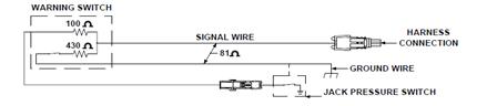 |
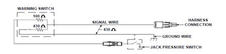
Figure 30
The 16,000 lb. and the 24,000 lb. straight-acting jacks did not use the new magnetic jack down warning switches. They used the existing side port warning switch and the 2″ plunger switch. These switches were not changed and did not have the two resistors. For these large jacks, a warning switch, pressure switch interface adaptor that had the 420 ohm and 100 ohm resistors was used. Refer to Figure 15 & Figure 20 in LESSON 9 – “Electronics and HWH®” to review these components. When replacing an older 16,000 lb. or 24,000 lb. jack cylinder, the new cylinder will use the new style magnetic warning switch instead of the original side port or plunger style switches.
The jack pressure switch is new with the 610 Series leveling system. As you should have learned by now, after an automatic leveling system has extended jacks to level the vehicle, the system performs a stabilizing procedure where jacks not used for leveling are extended to the ground to stabilize the vehicle. The jack pressure switch is used to signal the control box that the foot of the jack is on the ground and lifting the vehicle slightly during the stabilize procedure.
The jack pressure switch is a ¾ inch hex shaped, single wire switch that is attached to the barrel of the jack. The very first switches had no rubber boot to protect the interior of the switch. Shortly after HWH® started making these switches, we added the rubber boot to protect the switch. The present day switch has a sealing washer to protect the switch and the rubber boot is no longer used. See Figure 28 in this chapter for a view of the early and present day pressure switches along with several different mounting locations.
The jack pressure switches, like the warning switches, switch a ground for the control box. Like the warning switches, it is critical that the jack pressure switch has a good ground. The ground for the pressure switch comes from the connection of the pressure switch to the barrel of the jack. All of the jacks used at the time this system was available, were either kick-down jacks or straight-acting jacks that pivoted slightly. The pivot points of either style jack were a possible weak link in the ground circuit because of corrosion or dirt in the pivot point. This will be addressed when we discuss system ground enhancements.
The jack pressure switches are adjustable. The jacks used for stabilizing should lift the vehicle slightly to combat the effects of thermal contraction of fluid. A jack that is extending to stabilize a vehicle should lift the vehicle approximately ½ inch after touching the ground. Less than ½ inch lift can cause an issue due to thermal contraction. Too much lift can put the vehicle in an out of level position. Pressure switches are adjustable. The pressure switch is adjusted by unplugging the switch, removing the rubber boot (if so equipped), loosening the jam nut and turning the threaded adjusting body. Turning the adjusting body clockwise will increase the pressure and raise the vehicle more. Turning the adjusting body counterclockwise will decrease the pressure, allowing less lift. The jam nut should be tightened and the rubber boot replaced after adjustment. Use caution when removing or replacing rubber boot so the wire connection to the switch is not damaged. There is a switch adjustment sheet on the HWH® web site under Tech Support, Manuals, Online School. Go to “Bulletins-Service/Install/Operation/Product Information”. The adjustment sheet MI9544 is under the heading “Switches”.
610 Series system ground enhancements. There is a ground enhancement instruction manual under the same heading as the pressure switch adjustment sheet. The manual number is ML10906 – Ground Enhancement Instructions for 610 Series Non-Central Ground Systems. These “enhancements” have to be made because of the grounding issues that were encountered. There were possible corrosion problems with the jack mountings and the pivot points of the jacks. There could be corrosion or paint problems with the vehicle frame. Even ground points that would seem to be ok had to be changed. This was especially true for the control box.
The ground enhancements basically bring the control box, jack warning switches and the jack pressure switches to the same point, the chassis frame rails. The warning switch ground wire was moved from the jack pivot bracket to the frame rail. The warning switches and band clamps that attached the switches to the jacks were changed so they supplied a frame ground for the barrel of the jack that the jack pressure switch is mounted to. For the larger jacks that did not use a three wire warning switch, a small band clamp with a ground wire could be added directly to the jack pressure switch so the pressure switch could be grounded to the frame rail and supply a good ground for the pressure switch and the warning switch. The control box ground wire was moved to the frame rail by itself, even if the existing ground point was a good ground. Because the main battery ground is normally attached to one of the frame rails, sometimes it was necessary to bind the two frame rails together with a battery cable. Corrosion or paint on the cross members of the frame rail would sometimes cause a grounding issue. A couple of very important things that had to be done when performing these enhancements was the surface a ground wire was to be attached to had to be cleaned of corrosion and paint down to the bare metal before the connection was made and after the connection was made, the connection had to be protected from corrosion with some type of sealant. When the enhancements are done properly, the system performs properly.
The hydraulic pump/manifold assembly was a major difference between the older leveling systems and the 610 system. For systems with kick-down style jacks, the horizontal/vertical valve was eliminated. With the addition of the jack pressure switch, the stabilize valve was also eliminated. That was two less valves to worry about wiring. The solenoid valves for the 610 Series system were one wire valves that had an internally grounded coil. The one-wire valves are no longer available and an adaptor wire assembly must be used when replacing a one wire valve. The internal grounding of the solenoid valve along with the manifold now being mounted directly to the pump required the pump to have a good frame ground. The motor for the majority of pumps that were used at this time had two studs on the back plate, one for positive voltage and the other was ground. Originally, the ground stud did not need a cable. The ground stud was not isolated from the motor case so the ground for the motor was supplied by the pump mounting. The manifold pressure switch was also grounded at the motor ground stud. It was discovered that the ground stud would sometimes become loose from the motor case and cause ground issues. We added a ground cable to the stud to take care of the issue. The addition of the cable was part of the ground enhancements that we started doing and is covered in the ground enhancement manual, ML10906. If the pump motor being used did not have a ground stud, the ground cable was not necessary.
The Master Relay and Pump Relay is the same basic arrangement as used with the 510 Series systems. Both the master and pump relays are controlled with a switched +12 volt signal supplied by the control box. The master relay is turned on whenever the touch panel is on. The pump relay is turned on any time an operation requires a jack to be extended. The 610 Series systems used 2 continuous duty relays but were a different brand of relay than the early 510 Series and 400 Series systems used. The present day relay assembly with a continuous duty master relay and an intermittent duty pump relay can be used to replace the original relay assembly. The ground wires for the relays connected to the ground stud on the pump with the pressure switch wire and the grounding battery cable.
Sensing units for the 610 Series systems used a five-wire harness and was the same sensing unit as the 510 system used. One of the five wires is a ground for the sensing unit. The other 4 wires were the signal wires. Each wire controls one yellow level light. The sensing unit is mounted in a cross position to read the sides or ends of the vehicle. The sensing unit also has an “UP” position. The sensing units have a sticker that indicates the proper mounting direction and the UP side of the sensing unit. There are three mounting screws with a spring between the sensing unit and mounting surface at each screw. The mounting screws are also the adjusting screws. The original sensing units have mercury bulbs as part of the assembly and are not available any more. |
Figure 31 |

A new style electronic sensing unit can be used to replace the original sensing unit but will need an adaptor harness kit so it will function properly. Contact HWH® Technical Service for assistance.
The hydraulics for the 610 Series systems is quite a bit different than the two earlier automatic systems. The system uses the same kick-down style jacks as a manually controlled system. For the 610 Series system, there is only one hose that goes to each jack, kick-down or straight acting. As noted earlier, the pump and hydraulic manifold are now one assembly. (Except on the Blue Bird® buses.)
Power Unit Assembly. The pump and manifold assembly is referred to as the “power unit”. The manifold is bolted directly to the top of the pump, this eliminates the pressure and return lines between the pump and manifold. The assembly does take a little more room to install than just a pump but only one mounting location is needed instead of one for the pump and one for the manifold. The manifold still has a shuttle valve like the earlier systems and basically does the same thing, it isolates the pressure side from the return side. The 610 Series manifold has a check valve arrangement like the 510 Series manifold to allow two jack operation without the vehicle dropping. The manifold also has a 3,000 psi pressure switch like the other manifolds but is only used to indicate an “Excess Slope” situation during automatic leveling. The biggest difference is the manifold now only has four solenoid valves, one for each jack. There is no horizontal/vertical valve, there is not stabilize valve, there is no pressure reducing valve or flow switch and there is no bleed valve. The elimination of the bleed valve does cause an issue that will be discussed a little later. The solenoid valves are also different than the earlier systems. They are round and have a t-handle that is used to manually open the valve. The t-handle eliminates the need for drain valves. When the t-handles are opened, the fluid from the jacks drains directly back to the pump reservoir.
|

Figure 32
The schematic for the 610 Series system is quite a bit simpler than the earlier systems. The manifold still has a shuttle valve and the check valve arrangement is the same as the 510 Series system, but the 610 Series manifold has fewer solenoid valves and does not have a bleed valve on the horizontal/vertical circuit nor a pressure reducing valve/flow switch for the stabilizing procedure. No matter what type of jack is used, there is only one hose routed to each jack. The kick-down style jacks have the same type of kick-down actuator as the jacks used for manually controlled systems. Each jack does have a pressure switch that has not been used on any other system up to this time. One thing the schematic does not show is the solenoid valves are equipped with a t-handle to manually open the valve in the event of a failure. That is why no drain valves are shown in the hydraulic circuit. The schematic shown is for a system that is equipped with kick-down style jacks. |
Figure 33 |

Manual Leveling: The ignition key must be on or in the ACC. position and the park brake must be set. If the system uses kick-down jacks, the front of the vehicle should be the low end. Lifting the weight of the vehicle off of the rear wheels will allow the vehicle to roll off of kick-down jacks.
Note: If the vehicle is equipped with an air suspension, air should be dumped before a leveling procedure is started. If the vehicle has kick-down jacks, the air should be dumped after the jacks are in the vertical position. Push and hold the “DUMP” button until all air is exhausted from the vehicle suspension. The touch panel has to be on to use the “DUMP” button. The ignition must be on and the park brake has to be set.
Push the HYD (I) button. The red ON/LEVEL light should come on. The control box will send a +12 volt signal to turn the master relay on. The master relay supplies power to the pump relay. Any time an UP or DOWN ARROW button is pushed, the ON/LEVEL light will flash while the button is being held.
If the system has kick-down jacks, push the HYD (I) button a second time. The ON/LEVEL light will start to flash. The control box sends a +12 volt signal to the pump relay. The pump relay contacts will close and send +12 volts to the pump motor. The control box also sends a +12 signal to the jack solenoids to kick the jacks to a vertical position. The jacks will kick down in a specific sequence. The left front jack should kick down first, then the right front, the right rear and finally the left rear. The control box is looking for the jack warning switch to know the jack is in the vertical position. As the left front jack kicks down, its warning switch comes on sending a ground signal to the control box.
When the processor sees the signal, it turns the left front solenoid valve off and turns the right front solenoid valve on. The system continues this process until all four jacks are vertical with their warning switches on. The pump runs continuously while the jacks are extending to the vertical position. All four red jack down warning lights on the touch panel should be on.
If a jack does not go to a vertical position or its warning switch does not come on, the processor will wait three seconds then move to the next jack. If all four red warning lights are not on, the system will not continue to function in the automatic mode. The manual UP and Down arrows will still function. If an arrow that controls the jack that is not vertical is pushed, the red jack down warning light for that jack will flash while the button is being pushed.
If the system has straight-acting jacks or when the jacks are in the vertical position, the jacks can be extended to level the vehicle by pushing the UP ARROW (EXTEND) buttons. When an UP ARROW is pushed, the control box sends a +12 volt signal to the pump relay and the appropriate solenoid valves. The pump will push oil to those jacks and the jacks will extend until the button is released.
In manual operation, the system will always operate two jacks at the same time; both front jacks, both rear jacks, the left front and left rear jacks or the right front and right rear jacks.
The system level sensing unit sends ground signals to the control box to turn on yellow level lights. A lit level light indicates a side or end of the vehicle is low. One or two level lights can be on at the same time. Opposing level lights such as the front and the rear lights should not be on. Push and hold the appropriate UP ARROW buttons until the yellow lights are all out. It is recommended to level the vehicle side to side if needed before leveling the vehicle front to rear. To stabilize the vehicle, push and hold the front UP ARROW if one or both front jacks are not on the ground yet then push and hold the rear UP ARROW if one or both rear jacks are not on the ground yet. Jacks used to stabilize the vehicle should be extended until they lift the vehicle slightly, but not more than approximately ½ inch.
Manual Retract: The ignition must be in the ON or ACC position and the park brake must be set to manually retract the jacks.
Push the HYD (I) button. The red ON/LEVELING light should come on.
Retracting the jacks is the same for straight-acting or kick-down style jacks. Push and hold the DOWN ARROW (retract) buttons until the red jack down warning lights are out. Remember, the red warning light goes out with the foot of a straight-acting jack still extended one or two inches. Hold the DOWN ARROW buttons for five to ten seconds after the red warning lights go out. This will help make sure the foot of the jack is fully retracted. It is recommended to use the front down arrow to retract the front jacks first then the rear down arrow to retract the rear jacks. Larger jacks may take longer than five or ten seconds to fully retract.
At no time when a DOWN ARROW button is pushed or when the STORE button is pushed should the pump run. Single-acting jacks cannot retract if the pump is running.
The ignition must be in the ON or ACC. position. The park brake must be set. If the system uses kick-down jacks, the front of the vehicle should be the low end. Lifting the weight of the vehicle off of the rear wheels will allow the vehicle to roll off of kick-down jacks.
When the HYD (I) button is pushed the first time, this will turn the system on. The ON/LEVELING light will come on steady. One or two yellow level lights should be on at this time. The control box will turn the master relay on at this time. Like all automatic systems, there are two parts to leveling, first level the vehicle, all yellow level lights out, then stabilize the vehicle, make sure all four jacks are solidly on the ground. This is an important thing to remember for diagnostic issues.
If the system has kick-down jacks, push the HYD (I) button a second time. The ON/LEVELING light will start to flash. The control box will run the pump and open jack solenoid valves to extend the jacks to the vertical position in the same sequence as described in the SECTION 7-3 “610 Series – Manual Operation”. After all red warning lights come on, the ON/LEVEL light will stop flashing and will remain on steady.
If the system has straight- acting jacks, the leveling process, including dumping air from the suspension, starts when the HYD (I) button is pushed the second time.
Push the HYD (I) button a third time (second time if the vehicle is equipped with straight-acting jacks). The ON/LEVELING light will start to flash. The control box will first dump air from the suspension if so equipped. The control box supplies +12 volts to air dump solenoid valves. The system will dump air for approximately 25 seconds, and then start the leveling procedure. Some systems may have a longer air dump time. When the leveling procedure starts, the control box turns on the pump relay and the necessary solenoid valves to extend jacks according to lit yellow level lights. The system will turn out any lit side level light first and then a front or rear level light if lit.
Stabilizing: When all of the yellow level lights are out, the system will then stabilize the vehicle, that is, extend jacks not used to level the vehicle to the ground and lift slightly, approximately ½ inch. Each jack has a pressure switch. The switch supplies a ground signal to the control box when the jack is on the ground. The processor will turn the pump on and the solenoid valve for any jack pressure switch that is not on. When the processor sees a pressure switch signal, the processor will turn off the solenoid valve for that jack. When all four pressure switches are on, the system will turn the pump off and the system will shut off including all touch panel lights.
If a jack pressure switch does not come on, that jack will extend to full extension. This will cause the 3,000 psi manifold pressure switch to come on. Twenty seconds after the manifold pressure switch comes on, the processor will recognize there is a problem and turn off all pump and solenoid valve loads and turn the touch panel “EXCESS” light on. Depending on the specific program, the “EXCESS SLOPE” light will remain on until the ignition is turned off or will turn off approximately two minutes after it comes on.
In later versions of the 610 Series Non-central grounded system, the stabilize program was changed. Due to several issues including the type of chassis and the way kick-down actuators function, the front jacks would “walk” the front of the vehicle up as it tried to stabilize. The front pressure switches would turn off and on as the front jacks would bump the ground. To stop this, the program was changed so if either front jack pressure switch is off, both front valves are opened. The front jacks stabilize together. The jack that is already on the ground does not move. When the jack that is extending bumps the ground and the pressure switch comes on so both front jack pressure switches are on, both valves close. This keeps the front from “walking” up. The kick-down actuators were also redesigned to help with this issue.
Early model 610 systems with kick-down jacks can be upgraded. This requires a new control box and new actuators for the front jacks. Nothing was changed for the rear jacks. This same stabilize program is still used today on motorized vehicles.
Leveling programs. The early 610 Series systems had several different programs like the 510 Series system. Depending on the control box, the system would use 1, 2 or 3 jacks at the same time for leveling depending on which yellow level lights were on. Usually the one and two jack leveling programs were used with spring suspension vehicles. The three jack leveling program was used with air suspension vehicles. By the time the early 610 Series non-central grounded system was being phased out, most programs were two jacks at a time no matter what yellow level light or lights were on. Starting with the 610 central grounded system up to and including today’s present system, almost all motorized systems use the two jack at a time leveling program. There are only a couple special systems that do not use this program and would not be seen on the normal motor home or special use motorized vehicle.
Additional information for the 610 Series systems
- Excess Slope: Excess slope is when one or two jacks, depending on the stabilizing program, become fully extended with their yellow level lights remaining on. There is an indicator light for excess slope on the touch panel. See Figure 27. When a jack or jacks becomes fully extended and a level light stays on, the pressure in the system will build up until the 3000 psi manifold pressure switch turns on. This sends a ground signal to the control box. The system will not stabilize the vehicle if the “Excess Slope” light comes on. The “Excess Slope” light will stay on for two minutes then the panel will turn off.
- Low Volts: The touch panels are equipped with a red low volts BATTERY symbol at the top center of the touch panel. This light will come on if the voltage to the control box drops below approximately 8.5 volts. If the LOW VOLTS light comes on, all leveling process will stop.
- Master Warning Light: Most vehicles will have a master “JACKS DOWN” warning light that will be on anytime one or more individual red jack down warning lights are on. The master warning light is controlled with a switched ground from the control box. Power for the light is usually supplied by the control box but can be supplied from the ACC. side of the ignition switch.
- Leveling Programs: Leveling programs have evolved and changed over the years. This is especially true of early leveling systems. Because the original programs have been changed and updated for some control boxes, it is possible to run into an older system that may seem to act differently than the way the systems have been explained in this lesson. If you encounter this, contact HWH® for assistance.
The 610 Series Central Ground Series leveling system was designed to eliminate grounding issues with the original 610 Series leveling system. The electronics for the original 610 Series system was very dependant on maintaining constant voltage levels. Maintaining constant voltage levels is very dependant on maintaining good, consistent grounds throughout the system’s electrical circuit. Due to the basic nature of motor homes and chassis construction, maintaining these constant grounds was a difficult task. As noted in the previous chapter, we developed a grounding enhancement procedure that allowed the early 610 Series systems to function properly.
To eliminate the grounding issues, we developed the new system without using most of the solid state components that were incorporated into the early system. The 610 Series central ground control box uses relays that are more robust and not affected as much by the inconsistent grounds that can be encountered with motor home chassis. Wiring was also changed so all electrical components including the control box are grounded at one central point, a ground stud located at the pump. This did require a good, solid frame mount for the pump or a ground strap from the pump ground stud to the frame of the vehicle.
From a user standpoint, there are very few differences, if any, that would be noticeable. All programs for the new 610 Series use two jacks at a time for leveling and stabilize the two front jacks together. The touch panel looks the same as the early 610 Series system and the new system operates the same as the early system. The early 610 Series system was replaced by the 610 Series Central Ground system in late 1993.
The 610 Series central ground system, like most of our leveling systems, used quite a few different versions of the control box. There were programming differences because of the type of jacks or vehicle suspension used. When replacing a control box, it is correct to get the correct part number.
The best way to identify the 610 Series central ground system is to check the touch panel cable and the warning switch/pressure switch harness at any one of the jacks. The cable between the control box and the touch panel is a cable assembly with nine wires and an 11 pin MTA connector at each end. The harness at each jack had two connectors. A single pin Packard connector for the jack pressure switch and a two pin Packard connector for the jack down warning switch. The 610 Series central ground control box is also one inch longer than the original 610 Series control box.
610 SERIES CENTRAL GROUND SERIES CONTROL BOX AND TOUCH PANEL
|

Figure 34
The jack pressure switch is a feature introduced on the 610 Series Non-Central Grounded system. The jack pressure switch is used to let the control box know its jack is on the ground during the stabilize procedure. The pressure switch is mounted to the barrel of the jack. It is easily located on kick-down style jacks. On straight-acting jacks, it is mounted to the top of the jack barrel or lower on the side of the jack barrel. Early jack pressure switches did not have the rubber boot shown in Figure 35. A present day pressure switch that would replace an original switch does not have the rubber boot but has a sealing washer between the body of the switch and the adjusting jam nut. Refer to Figure 35 for views of the pressure switch and several pressure switch mountings.
Pressure Switches |
9,000 lb. |
Straight-Acting Jack |
Straight-Acting Jack |
| |||

Figure 35
The basic electrical functions of the 610 Series Central Ground systems are not much different than the original 610 Series modular cable systems. The touch panel has multi-plexed communications with the control box. Information inputs and control outputs are routed to or from the control box. Information inputs are ground signals and control outputs are +12 volt signals. The warning switches are still a crucial part of the system when kick-down style jacks are used. Each jack still has a pressure switch which is used to complete a stabilizing process during automatic leveling. The main difference electrically is the jack warning switches and pressure switches are routed to the control box on separate circuits instead of the same circuit for each jack. The jack now uses a simple two wire warning switch. The term “Central Ground” comes from all grounds for the jack switches, solenoid valves and the control box are routed to one central location at the hydraulic power unit. The grounds attach to a ground stud that is used to mount the power unit or can be screwed directly into the power unit. It is easier to control the grounds for the system because now all that has to be maintained is a good frame ground for the power unit. This can be the power unit mounting bracket or could be a ground cable from the power unit to the frame of the vehicle. In many cases, erratic or improper system operation can be traced to a weak ground connection for the power unit to the frame of the vehicle.
There are two repair manuals for the 610 Series Central Ground systems, the ML1679 for systems with kick-down jacks and the ML1681 for systems with straight-acting jacks. These repair manuals have wiring diagrams for the control box as well as the complete system. These manuals are in the “Service/Diagnostics Manuals” section on the HWH® web site.
The 610 Series Central Ground Series system control box is shown in Figure 34. The control box uses two power sources. The control box uses ignition power (preferably from the ACC. side of the ignition switch) for the circuitry and processor in control box and touch panel functions. Ignition/ACC. power is routed to the three pin UML connector on the fuse end of the control box. The +12 power to operate the hydraulic solenoid valves comes from a #10 wire that is routed to the switched side of the master relay on the hydraulic pump motor. This wire was protected with a 40 amp fuse. At the control box, the #10 wire is split into three #12 wires that are routed into the six pin UML connector on the fuse side of the control box. This wire should only have power if the touch panel is on. The control box ground is routed from the power unit ground stud to a ¼” stud on the fuse end of the control box. Solenoid valve outputs, air dump output and the manifold pressure switch input are routed to the nine pin UML connector on the fuse side of the box. The master and pump relay outputs along with the park brake input are routed to the six pin UML connector on the fuse side of the control box. The touch panel cable connection, the sensing unit inputs and the jack warning switch and pressure switch inputs are routed to the other end of the control box. The jack pressure switch and warning switch inputs are in the same connector. There is also a connector for inputs from HWH® slide-out room extension controls on this end of the control box.
The 610 Central Ground touch panel has the same Lexan as the original 610 Series touch panel. Refer to Figure 34 for a view of the touch panel. Refer to Figure 22 for complete information about the touch panel buttons and indicator lights. The touch panel cable for the 610 Series Central Ground system was a cable assembly with nine wires and an 11 pin MTA connector on each end. The connector is keyed so the cable cannot be plugged in upside down. This cable was available in many different lengths.
Jack Down Warning Switches. The 610 Series Central Ground systems do not use the three-wire warning switches with resistors like the original 610 Series system did. The kick-down jacks use a two-wire tilt switch with a two-pin Packard connector. The straight-acting jacks will have several different switches depending on the jack. The 24,000# straight-acting jacks will use a single wire two inch plunger switch. Some of the other jacks will use a single wire side port warning switch. The majority of the jacks will use the two-wire magnetic warning switch. Refer to Figure 21 for a view of the two inch plunger warning switch and the side-port warning switch. Figure 36 shows the two-wire tilt warning switch and the two-wire magnetic warning switch. The current tilt switch has a short ground wire that mounts between the lock washer and the switch where the switch screws to the jack. The current magnetic switch has a short wire soldered from the main switch ground wire to the top of the warning switch. These wires ensure the barrel of the jack will have a good ground for the jack pressure switch. The existing switches on older jacks may not have these ground wires. |
Figure 36 |
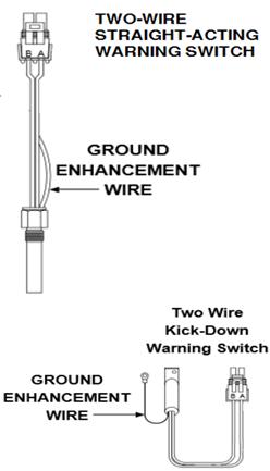
Note: Refer to “Electronics and HWH®” for a detailed explanation of all jack warning switches. The existing magnetic warning switch for straight-acting jacks will most likely have a black Packard connector. The replacement switch will have a gray connector. An adaptor will be needed to make the connection to the existing harness.
The jack pressure switch was first used with the original 610 Series leveling system. Like all automatic systems, after the system has extended jacks to level the vehicle, the system performs a stabilizing procedure where jacks not used for leveling are extended to the ground to stabilize the vehicle. The jack pressure switch is used to signal the control box that the foot of the jack is on the ground and lifting the vehicle slightly during the stabilize procedure.
The jack pressure switch is a ¾ inch hex shaped, single wire switch that is attached to the barrel of the jack. The original switches will have a rubber boot to protect the interior of the switch. The current jack pressure switches have a sealing washer to protect the switch and the rubber boot is no longer used. See Figure 35 in this chapter for a view of the early and present day pressure switches along with several different mounting locations.
The jack pressure switches, like the warning switches, switch a ground for the control box. Like the warning switches, it is critical that the jack pressure switch has a good ground. The ground for the pressure switch comes from the connection of the pressure switch to the barrel of the jack. All of the jacks used with this system, were either kick-down jacks or straight-acting jacks that pivoted slightly. The pivot points of the jacks were a possible weak link in the ground circuit because of corrosion or dirt in the pivot point. This is why the ground enhancement wire was added to the jacks warning switches.
The jack pressure switches are adjustable. The jacks used for stabilizing should lift the vehicle slightly to combat the effects of thermal contraction of fluid. A jack that is extending to stabilize a vehicle should lift the vehicle approximately ½ inch after touching the ground. Less than ½ inch could cause an issue with stability due to thermal contraction of the fluid. Too much lift will put the vehicle in an out of level position. If the pressure switch is set to high, the vehicle will raise too high. If the switch is set too low, the jack will not lift the vehicle enough. The pressure switch is adjusted by unplugging the switch, removing the rubber boot (if so equipped), loosening the jam nut and turning the threaded adjusting body. Turning the adjusting body clockwise will increase the pressure and raise the vehicle more. Turning the adjusting body counterclockwise will decrease the pressure, allowing less lift. The jam nut should be tightened and the rubber boot replaced after adjustment. Use caution when removing or replacing rubber boot so the wire connection to the switch is not damaged. There is a switch adjustment sheet on the HWH® web site under Customer Support and Technical Service. Go to “Bulletins-Service/Install/Operation/Product Information”. The adjustment sheet MI9544 is under the heading “Switches”.
The hydraulic pump/manifold assembly is almost identical to the assembly used with the original 610 Series systems. The difference would be the relays on the pump motor and the grounding of the pump motor. The manifold uses the same valves and pressure switches. The original 610 systems used a continuous duty relay for both the master and pump relay. The pump motor had an external ground stud. The motor now uses a continuous duty master relay and an intermittent duty pump relay. The pump motor is internally grounded and relies on a good frame ground. This can be through the mounting bracket or done with a ground cable from the pump ground stud to the frame. If a ground cable is needed, it should be the same gauge wire that is used to supply voltage to the pump.
The Master Relay and Pump Relays are a little different than what was used on the original 610 Series systems. Instead of two continuous duty relays, the master relay is still a continuous duty relay but the pump relay is now an intermittent duty relay. Both the master and pump relays are controlled with a switched +12 volt signal supplied by the control box. The master relay is turned on whenever the touch panel is on. The pump relay is turned on any time an operation requires a jack to be extended or the pump is needed for a room extension operation. Four post relays are used. The two small posts are for the coil and the two large posts are power in/out contacts. The coil and contact posts are non-directional. The ground wires for the relay coils are connected to the ground stud on the pump with the grounding battery cable (if required), solenoid valve grounds and the control box ground wire.
Sensing units for the 610 Series Central Ground Series systems are the same five-wire sensing units as the original 610 Series systems used. One wire is a ground for the sensing unit. The other four wires were the signal wires. Each wire controls one yellow level light. The sensing unit is mounted in a cross position to read the sides or ends of the vehicle. The sensing unit also has an “UP” position. The sensing units have a sticker that indicates the proper mounting direction and the UP side of the sensing unit. There are three mounting screws with a spring between the sensing unit and mounting surface at each screw. The mounting screws are also the adjusting screws. The original sensing units have mercury bulbs in the assembly and are no longer available. |
Figure 37 |
Note: A new style electronic sensing unit can be used to replace the original sensing unit but will need an adaptor harness kit to supply power. Contact HWH® Technical Service for assistance.
Hydraulically the 610 Series Central Ground systems are the same as the original 610 Series systems. HWH® started developing and selling slide-out mechanisms when the 610 Series Central Ground systems were in production but this did not change the hydraulic arrangement of the 610 Series Central Ground leveling systems. If HWH® slide-outs were used, a slide-out manifold was added to the power unit between the leveling manifold and the pump.
Power Unit Assembly. The pump and manifold assembly is referred to as the “power unit” or hydraulic control unit. Except for the motor and relay arrangements, the 610 Series Central Ground power unit is the same as the original 610 Series assembly. Functionally, they are exactly the same. The manifold/valve assembly is bolted directly to the top of the pump. If the vehicle is equipped with HWH® slide-out mechanisms, the slide-out manifold assembly mounts to the power unit between the leveling system manifold and the top of the pump. The manifold has a shuttle valve that isolates the pressure side from the return side. The 610 Series manifold has a check valve arrangement to allow two jack operation without the vehicle dropping. The manifold also has a 3,000 psi pressure switch like the other manifolds but is only used to indicate an “Excess Slope” situation during automatic leveling. All of the earlier 610 Series Central Ground systems will use the large 2.25″ diameter solenoid valve. The existing solenoid valves will have the manual valve release t-handle but can use the new solenoid valve with the cam release as a direct replacement. When the t-handles are opened, the fluid from the jacks drains directly back to the pump reservoir. A few later 610 systems that have 6,000# jacks may have the smaller 1.5″ diameter solenoid valve with the ¼ inch release nut for manually opening the valve. This can be replaced with the new small valve that has the valve release cam. It is not recommended to replace a large valve with a small valve or visa-versa. The valves have a different flow rate and can affect the performance of the leveling system.
Figure 38 |

The schematics for the 610 Series Central Ground systems are exactly the same as the original 610 Series systems. Only four solenoid valves are used. There is a shuttle valve and two check valves for each solenoid valve. There is a 3,000# pressure switch. No matter what type of jack is used, there is only one hose routed to each jack. The kick-down style jacks have the same type of kick-down actuator as the jacks use for manually controlled systems. Each jack has a pressure switch used during the stabilizing operation of automatic leveling. One thing the schematic does not show is the solenoid valves are equipped with a t-handle to manually open the valve in the event of a failure. That is why no drain valves are shown in the hydraulic circuit. The schematic shown is for a system that is equipped with kick-down style jacks. |
Figure 39 |
Manual Leveling: The ignition key must be on or in the ACC. position and the park brake must be set. If the system uses kick-down jacks, the front of the vehicle should be the low end. Lifting the weight of the vehicle off of the rear wheels will allow the vehicle to roll off of kick-down jacks.
Note: If the vehicle is equipped with an air suspension, air should be dumped before a leveling procedure is started. If the vehicle has kick-down jacks, the air should be dumped after the jacks are in the vertical position. Push and hold the “DUMP” button until all air is exhausted from the vehicle suspension. The touch panel must be on to use the “DUMP” button. The ignition must be on and the park brake set. See “Additional Information for the 610 Series System” for pilot air dump information.
Push the HYD (I) button. The red ON/AUTO light should come on. The control box will send a +12 volt signal to turn the master relay on. The master relay supplies power to the pump relay. Any time an UP or DOWN ARROW button is pushed, the ON/AUTO light will flash while the button is being held.
If the system has kick-down jacks, push the HYD (I) button a second time. The ON/AUTO light will start to flash. The control box sends a +12 volt signal to the pump relay. The pump relay contacts will close and send +12 volts to the pump motor. The control box also sends a +12 signal to the jack solenoids to kick the jacks to a vertical position. The jacks will kick down in a specific sequence. The left front jack should kick down first, then the right front, the right rear and finally the left rear. The control box is looking for the jack warning switch to know the jack is in the vertical position. As the left front jack kicks down, its warning switch comes on sending a ground signal to the control box. When the processor sees the signal, it turns the left front solenoid valve off and turns the right front solenoid valve on. The system continues this process until all four jacks are vertical with their warning switches on.
The pump runs continuously while the jacks are extending to the vertical position. All four red jack down warning lights on the touch panel should be on. The system will most likely have a master “JACKS DOWN” warning light located on the dash. This light will come one as soon as the first jack is vertical with its red warning light on.
If a jack does not go to a vertical position or its warning switch does not come on, the processor will wait three seconds then move to the next jack. If all four red warning lights are not on, the system will not continue to function in the automatic mode. The manual UP and Down arrows will still function. If an arrow that controls the jack that is not vertical is pushed, the red jack down warning light for that jack will flash while the button is being pushed.
If the system has straight-acting jacks or when the jacks are in the vertical position, the jacks can be extended to level the vehicle by pushing the UP ARROW (EXTEND) buttons. When an UP ARROW is pushed, the control box sends a +12 volt signal to the pump relay and the appropriate solenoid valves. The pump will push oil to those jacks and the jacks will extend until the button is released.
In manual operation, the system will always operate two jacks at the same time; both front jacks, both rear jacks, the left front and left rear jacks or the right front and right rear jacks.
The system level sensing unit sends ground signals to the control box to turn on yellow level lights. A lit level light indicates a side or end of the vehicle is low. One or two level lights can be on at the same time. Opposing level lights such as the front and the rear lights should not be on. Push and hold the appropriate UP ARROW buttons until the yellow lights are all out. It is recommended to level the vehicle side to side if needed before leveling the vehicle front to rear. To stabilize the vehicle, push and hold the front UP ARROW if one or both front jacks are not on the ground. Then push and hold the rear UP ARROW if one or both rear jacks are not on the ground. Jacks used to stabilize the vehicle should be extended until they lift the vehicle slightly, but not more than approximately ½ inch.
Manual Retract: The ignition must be in the ON or ACC position and the park brake must be set to manually retract the jacks. Some later 610 Series systems did not have to have the park brake set.
Push the HYD (I) button. The red ON/AUTO light should come on.
Retracting the jacks is the same for straight-acting or kick-down style jacks. Push and hold the DOWN ARROW (retract) buttons until the red jack down warning lights are out. It is recommended to retract the front jacks before retracting the rear jacks. This is especially true for vehicles that have an air dump system. When the rear of the vehicle lowers, the chassis tends to roll forward. When the rear rises, the chassis rolls backward. Retracting the front jacks first keeps the front jacks from “dragging” as the rear of the vehicle lowers. Remember, the red warning light goes out with the foot of a straight-acting jack still extended one to two inches. Hold the DOWN ARROW buttons for five to ten seconds after the red warning lights go out. This will help make sure the foot of the jack is fully retracted. Larger jacks may take longer than five or ten seconds to fully retract.
At no time when a DOWN ARROW button is pushed or when the STORE button is pushed should the pump run. Single-acting jacks cannot retract if the pump is running.
The ignition must be in the ON or ACC. position. The park brake must be set. If the system uses kick-down jacks, the front of the vehicle should be the low end. Lifting the weight of the vehicle off of the rear wheels will allow the vehicle to roll off of kick-down jacks.
When the HYD (I) button is pushed the first time, this will turn the system on. The ON/AUTO light will come on steady. One or two yellow level lights should be on at this time. The control box will turn the master relay on at this time. Like all automatic systems, there are two parts to leveling, first level the vehicle, all yellow level lights out, then stabilize the vehicle, make sure all four jacks are solidly on the ground. This is an important thing to remember for diagnostic issues.
If the system has kick-down jacks, push the HYD (I) button a second time. The ON/AUTO light will start to flash. The control box will run the pump and open jack solenoid valves to extend the jacks to the vertical position in the same sequence as described in the SECTION 8-3 “610 Central Ground Series – Manual Operation”. After all red warning lights come on, the ON/AUTO light will stop flashing and will remain on steady. The master “JACKS DOWN” warning light should be on.
If the system has straight- acting jacks, the leveling process, including dumping air from the suspension, starts when the HYD (I) button is pushed the second time.
Push the HYD (I) button a third time (second time if the vehicle is equipped with straight-acting jacks). The ON/AUTO light will start to flash. The control box will first dump air from the suspension if so equipped. The control box supplies +12 volts to air dump solenoid valves. The system will dump air for approximately 25 seconds, and then start the leveling procedure. Some systems may have a longer air dump time. When the leveling procedure starts, the control box turns on the pump relay and the necessary solenoid valves to extend jacks according to lit yellow level lights. The system will turn out any lit side level light first and then a front or rear level light if lit.
Stabilizing: When all of the yellow level lights are out, the system will then stabilize the vehicle, that is, extend jacks not used to level the vehicle to the ground and lift slightly, approximately ½ inch. Each jack has a pressure switch. The switch supplies a ground signal to the control box when the jack is on the ground. The processor will turn the pump on and the solenoid valve for any jack pressure switch that is not on. When the processor sees a pressure switch signal, the processor will turn off the solenoid valve for that jack. When all four pressure switches are on, the system will turn the pump off and the system will shut off including all touch panel lights.
If a jack pressure switch does not come on, that jack will extend to full extension. This will cause the 3,000 psi manifold pressure switch to come on. Twenty seconds after the manifold pressure switch comes on, the processor will recognize there is a problem and turn off all pump and solenoid valve loads and turn the touch panel “EXCESS” light on. Depending on the specific program, the “EXCESS SLOPE” light will remain on until the ignition is turned off or will turn off approximately two minutes after it comes on.
When stabilizing, if either front jack pressure switch is off, both front valves are opened. The front jacks stabilize together. The jack that is already on the ground does not move. When the jack that is extending bumps the ground and the pressure switch comes on so both front jack pressure switches are on, both valves close. This keeps the front from “walking” up. The rear jacks are stabilized individually.
Leveling Programs. Like all systems, the 610 Series Central Ground Series had different programs. Unlike earlier systems, most of the programs run two jacks at a time no matter what type of chassis was used. Most of the program differences were due to the type of jack, kick-down or straight-acting and the type of suspension, spring or air bags. There were a few different programs due to jack size or some type of special leveling program required for a specific vehicle but the majority of programs used the simple two jack leveling program. One new program to deal with slide-outs was introduced with the 610 Series Central Ground system. If the slide-out room is a HWH® slide-out room, running the room interrupts the leveling and store procedures if the slide-out is operated.
- Excess Slope: Excess slope is when one or two jacks, depending on the stabilizing program, become fully extended with their yellow level lights remaining on. There is an indicator light for excess slope on the touch panel. See Figure 34. When a jack or jacks becomes fully extended and a level light stays on, the pressure in the system will build up until the 3000 psi manifold pressure switch turns on. This sends a ground signal to the control box. The system will not stabilize the vehicle if the “Excess Slope” light comes on. The “Excess Slope” light will stay on for 2 minutes then the panel will turn off.
- Low Volts: The touch panels are equipped with a red low volts BATTERY symbol at the top center of the touch panel. The use of this light was being phased out with the 610 Central Ground systems. If used, this light will come on if the voltage to the control box drops below approximately 8.5 volts. On some systems, if the LOW VOLTS light comes on, the leveling process will stop. As time progressed, if the light came on, the leveling process was not interrupted.
- Master Warning Light: Most vehicles will have a master “JACKS DOWN” warning light that will be on anytime one or more individual red jack down warning lights are on. The master warning light is controlled with a switched ground from the control box. Power for the light is usually supplied by the control box but can be supplied from the ACC. side of the ignition switch.
- Leveling Programs: Leveling programs have evolved and changed over the years. This is especially true of early leveling systems. Because the original programs have been changed and updated for some control boxes, it is possible to run into an older system that may seem to act differently than the way the systems have been explained in this lesson. If you encounter this, contact HWH® for assistance.
- Slide-Outs (room extensions): The first HWH® slide-outs were developed in 1995/96. There were special double control boxes made for some of these systems. They looked like 2 standard control boxes put together. The slide-out controls ran directly to the box and the box controlled all leveling and slide-out functions.
- Pilot Air Dump: Pilot air dump first started to be used around 1996. For a detailed explanation of Pilot Dump, see LESSON 4 – “Introduction to Air Suspensions” in our online technical school. CHAPTER 4 is on Pilot Air Dump. Basically, pilot air dump is a two position system, Dump or Travel. In the Dump position, the air bags are connected to an exhaust port and will not hold any air. In the Travel position, the bags are controlled by the height control valves. This means the valve has to be shifted to either Dump or Travel. You no longer have to hold the “DUMP” button to exhaust the system air. The button can be pushed and released. This puts the system in the Dump position. The same criterion holds for pilot dump. The ignition must be on, the panel must be on and the park brake must be set. Automatic leveling will also control pilot dump the same way it controls the HWH® air dump valves.
Pushing the “STORE” button will shift the pilot dump system to the Travel mode. To shift the system to Travel, the ignition must be on, the panel must be on and the park brake must be set. Like the other dump system, later boxes may not have to have the park brake set. Also if the ignition is on and the park brake is off, there is a constant signal to the pilot valve to keep it in the Dump position.
Systems with either the pilot dump system of the HWH® dump valves us the same touch panel. The difference would be the control box. Looking up the part number of the control box will tell you if the system has pilot air dump.
Good luck with the test. Remember, you can review the lesson as you take the test.