CHAPTER 1 – INTRODUCTION to HYDRAULICS
- 1-1 Introduction and Overview
- 1-2 Basic Hydraulic Principles
- 1-3 Hydraulic Calculations and Formulas
- 1-4 Hydraulic System Special Tools & Equipment
- 1-5 Basic Hydraulic Circuit
CHAPTER 1 – INTRODUCTION to HYDRAULICS
Hydraulics are used in many types of industry, from transportation to food processing. Applications vary from machines that are required to do heavy lifting to stopping vehicles. One reason for using hydraulics is that you can gain tremendous mechanical advantage. For example, with little effort on a jack handle, we can raise a large recreation vehicle, as shown in Figure 1-1. Another advantage of the hydraulic system is that it permits control from another location from where the work is performed. Similar to an electrical switch, a control in the hydraulic system can be activated to have the pump apply pressure to the system, while the work is conducted at another location, such as the slide out mechanism of an RV’s expandable room. Hydraulics have the advantage over an air operated system, because air is highly compressible where fluids have a very low compressibility. Therefore, forces and motion are more easily controlled.
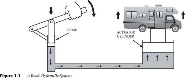 |
Figure 1-1 A Basic Hydraulic System
Regardless of the industry or the application, if you are involved in the maintenance of hydraulic equipment or systems, it is very important that you have an understanding of how the components in the systems operate and the hydraulic principles that make them function. Leveling systems, brakes and slide-out rooms are just some of the RV systems that utilize hydraulics.
1. Static pressure exerted by a column of fluid is proportional to the height of the top of the FLUID and is not affected by its volume, as illustrated in Figure 1-2. If we have different shaped containers, as shown, the pressure at the bottom of the containers will be the same, as long as the height of the fluid in the containers is the same. This is true regardless of the shape or volume of the container.
|
Equal height of fluid in a container will give equal pressure at the bottom of the container regardless of the shape of the container. |
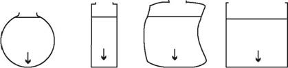
Figure 1-2 Static Pressure
2. Fluids (liquids) are relatively incompressible. While air can be compressed, fluid can only be compressed a very small amount.
3. Pascals law simply stated, is: “pressure in an enclosed container is transmitted equally and undiminished to all parts of the container and acts at right angles to the enclosing walls."
This is demonstrated in Figure 1-3. This is an important law and will be discussed in more detail, later in this book.
|
|

Figure 1-3 Pascal’s Law
4. Transmission of force is a little more complicated, but stated as simply as possible, under static conditions two large chambers connected by a small line will have the same pressure in both chambers.
|
A
|
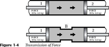
Figure 1-4 Transmission of Force
5. Mechanical advantage is demonstrated in Figure 1-5 below, and as stated earlier, is one of the main reasons for the use of hydraulics.
A force of 10 lbs. (4.5kg).
(F1) is being applied to a 1 square inch piston (6.5cm2) (A1).
The FLUID pressure of 10 pounds per square inch (psi) (69kPa) in the enclosed system is the same throughout the enclosed system.
(Pascal’s Law) Piston A2 is 10 square inches (65cm2), therefore, 10 PSI X 10sq. inches = 100 lbs. of force (69kPa X 65cm2=45kg) at F2.
We will show how the math is done later. The main thing here is to realize that we applied or “put in” a force of 10 lbs. (4.5kg) and received or “got out” a force of 100 lbs. (45kg). This is the mechanical advantage and basically explains how a hydraulic jack works.
|
|
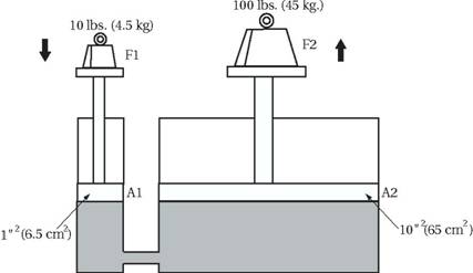
Figure 1-5 Mechanical Advantage
A force is a push or pull that is exerted on an object in order to change its position or direction of movement, as shown in Figure 1-6. In a hydraulic system, force must be present at all times for the system to function. Force can be calculated by multiplying the area times the pressure.
|
|
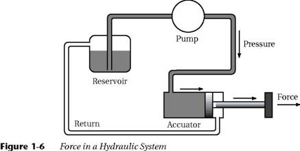
Figure 1-6 Force in a Hydraulic System
The weight of an object or substance is the result of the gravitational force or pull on the object. Weight is always a downward factor, and in a hydraulic system, the fluid in the reservoir, in the lines, or in any of the system components, have weight.
Mass is a factor common to all objects or substances. Mass represents the amount of matter in an object, and its inertia or resistance to movement. The mass of an object determines how much force is required to start, stop or change the movement of an object. The greater its mass, the more force is required to overcome its inertia.
Specific gravity is the density or mass of a liquid. The specific gravity (SG) of a liquid is also its weight as compared to the weight of water in the same amount and at the same temperature. The SG of water is 1.0, while petroleum-based hydraulic fluids have a SG of about 0.78, other types of hydraulic fluids may have a SG of 1.42. Although the SG of a fluid is usually not functionally important, it can be useful to help determine the type of hydraulic fluid present in a system.
Pressure is determined by dividing the force (in pounds) exerted on an object or a substance by the area (in square inches) over which the force is exerted, see Figure 1-7. Although pressures are measured and specified in different ways, the use of pounds per square inch (PSI), or kilopascals (kPa) is the most common. PSI always refers to the fluid pressure in a hydraulic system. Force can also be calculated by multiplying the pressure times the area.
|
|
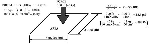
Figure 1-7 Determining Pressure
|
|
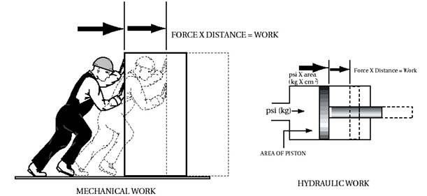
Figure 1-8 Mechanical vs. Hydraulic Work
Work takes place when a force (in pounds) is moved through a distance (in feet). The amount of work done is expressed in foot-pounds.
Earlier, we talked about mechanical advantage. It has a relationship with work, as shown in Figure 1-9. We put in 10 pounds (4.5 kg) of force and got out 100 pounds (45 kg) of force. That was great, but we all know you can’t get something for nothing. We had to give up something to gain the mechanical advantage. In this case, we gave up speed and distance. Let’s just consider the distance part. If we move the 1 square inch piston down 1 inch, 1 cubic inch of fluid (16cc) will be pushed into the A2 side of the system. Piston A2 is 10 square inches (65cm2). Therefore, if we spread that 1 cubic inch (16cc) out over 10 square inches (65cm2), we see that piston A2 will move up 1/10th of an inch (.25cm) (1 in3 ÷ 10 in2 = 0.1 in (16 cc ÷ 65 cm2 = 0.25 cm)). We gained force, but we gave up distance. Now, think of the jack again. We move the jack handle a greater distance than the object we are lifting moves up. That is where the speed comes in. We have to move the handle further and faster to lift the heavier object a reasonable distance. If we reversed the process and applied the 100 pounds of force to F2 we would only get 10 pounds of force out, but the speed and distance of piston A1 would be huge. Now you can see how we can move objects by working small pistons versus large ones.
|
|
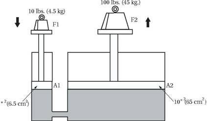
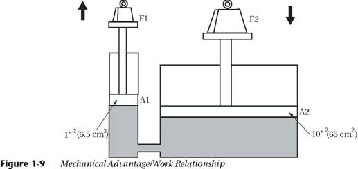
Figure 1-9 Mechanical Advantage / Work Relationship
Power is defined as an amount of work (foot-pounds) done in a given amount of time (seconds or minutes). In order to get some meaning from the term power, it must be compared with some unit of measure. The common unit of measure for power is the horsepower, which is expressed as follows:
|
1 Horsepower = 33,000 foot-pounds/one minute |
Energy is the capacity for doing work.
There are several types of energy used in hydraulic systems, including:
- Electrical Energy – to operate the pump motor.
- Hydraulic Energy – produced by the pump.
- Kinetic Energy – produced when the hydraulic fluid moves a piston in a cylinder.
- Potential Energy – present before the cylinder piston has moved the object.
- Heat Energy – produced by friction in the pump motor, pump, piston and hydraulic fluid.
In hydraulic systems, energy in the form of pressurized liquid flow is controlled and transmitted through a piping system, to a hydraulic actuator, at the point of work as shown in Figure 1-10.
|
|
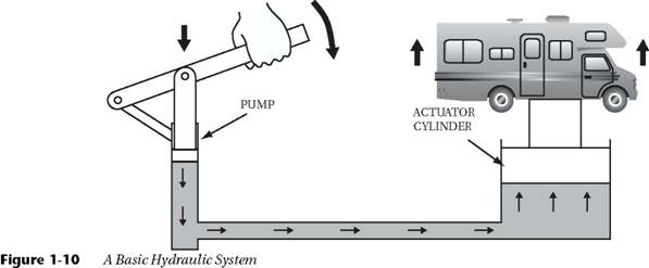
Figure 1-10 A Basic Hydraulic System
Examination of the effects of fluid pressure exerted on a confined vessel shows that the applied pressure is transmitted equally in all directions throughout the fluid. In contrast, if a solid block of wood were to be pushed on one of its ends, the effect of the force would be transmitted only in a straight line, as shown in Figure 1-11. In a hydraulic system, fluid pressure is applied against all interior surfaces of all components equally, as shown in Figure 1-12. This concept is the essence of Pascal’s Law, and applies to all fluid power equipment.
Note: According to Pascal’s Law, pressure on a confined fluid is transmitted undiminished in every direction to the surface(s) of the containing vessel (see Figure 1-12).
|
|
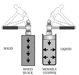
Figure 1-11 Pascal’s Law
|
|
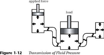
Figure 1-12 Transmission of Fluid Pressure
The flow of fluid in a hydraulic system is the means used for transferring the applied pressure through the system to cause work to be conducted. When the system is properly designed, the fluid flow through the system is smooth and efficient. This is referred to as laminar flow. If the system has too small of a line, kinked lines or sharp bends, the result is turbulent flow.
Streamline or laminar flow, is the ideal type of fluid flow in a hydraulic system, because all the particles of fluid move in parallel lines, as depicted in Figure 1-13. During the flow, the layer of fluid next to the surface of the pipe moves the slowest, because of friction between the fluid and the pipe, or other containment device. Each inner layer of fluid slides along the next outer layer of fluid with less and less friction until the fluid layers near the center of the flow passage move the fastest. Laminar flow results from low fluid friction. The lower the friction, the less heat is generated within the hydraulic system and the more efficient the system will operate.
|
|
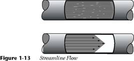
Figure 1-13 Streamline Flow
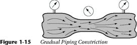
Turbulent flow conditions usually occur because the fluid passage is too small for the required flow velocity, or because the viscosity of the hydraulic fluid is too low. Also, rough or irregularly formed fluid passages (e.g., kinks in lines or sharp bends), sudden enlargements or reductions in the diameter of the fluid passages, and sudden changes in the direction of flow, contribute to turbulence and should be avoided (see Figure 1-14 and Figure 1-15).
|
|
|
|
Figure 1-14 Turbulent Flow |
Figure 1-15 Gradual Piping Construction |
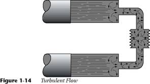
Turbulent flow heats up the hydraulic fluid more than laminar flow. It wastes power by requiring more fluid pressure. In addition, turbulent flow can release the air that is suspended in the hydraulic fluid, thus forming large bubbles or pockets in the lines and components. This is called cavitation. Cavitation is undesirable because air bubbles make the hydraulic system sluggish and less responsive. Cavitation can also cause internal damage and accelerated wear to components.
Damage to components may result because the hydraulic system components not only move the fluids within the system, but also use the fluids for lubrication of the internal components. Air bubbles within the system cause internal components to wear due to the absence of fluid. Larger air pockets in the system can render a hydraulic system completely inoperable.
- VISCOSITY: Viscosity is the resistance of a fluid to flow.
- FLUIDITY: Fluidity is the ability of the fluid to take the shape of the container it is in.
- FLASH POINT: The lowest temperature at which vapors from a volatile liquid will ignite. When a fluid is heated to a point it becomes flammable, it has reached its flash point.
- INCOMPRESSIBLE FLUID: A fluid which is not reduced in volume by an increase in pressure. All liquids are compressible to a small degree.
- THERMAL EXPANSION: The dimensional changes in increased volume exhibited by solids, liquids, and gases for changes in temperature while pressure is held constant. All liquids tend to expand when heated. Some liquids expand more than others.
A good hydraulic fluid should have a high flash point and a viscosity that will allow it to flow easily through the system. Liquids tend to expand when they are heated, and if hydraulic fluid is placed in a completely closed vessel and heated, it will exert greater pressure on all interior surfaces of the vessel. As liquids are incompressible, a great deal of damage could result if the pressure became too great. Heat also causes hydraulic fluids to thin out. If they are thinned out too much, the maximum pressure that the pump can develop may be reduced. In many cases, heat causes seals and packings to leak, because of the lowered fluid viscosity. Ultimately, the heat will cause the fluid to deteriorate. It is obvious that unnecessary heating of the fluid in a hydraulic system must be avoided, and cooling systems should be used whenever necessary. Thermal relief valves are used in systems where heated fluid damage may occur.
There are three basic types of hydraulic fluid.
- Vegetable fluid has an alcohol and castor oil base.
- Mineral fluid has a petroleum base.
- Synthetic fluid has a phosphate ester base. It is used where a fire resistant fluid must be used.
Note: The important thing is that fluids can not be mixed. Each type of fluid has its own compatible seals. It is extremely important to determine the type of fluid being used in the system you’re servicing by reading the manual or checking with the manufacturer. HWH® Hydraulic Oil is recommended for HWH® hydraulic systems because it is formulated to conform to HWH requirements.
Modern industrial equipment makes use of many fluid power systems that are used to transmit force through a fluid to perform work. The fluid can be either a liquid, such as water or oil, or a gas, such as compressed air, nitrogen or carbon dioxide. A system that uses gas as the transmitting force is called a pneumatic system. A system that uses a liquid as the transmitting force is called a hydraulic system. For almost all machines, the energy that does the ultimate work is mechanical energy. Even other forms of energy transmission generally result in mechanical energy. For this reason, they require an actuator before the point of work. Actuators transform hydraulic energy into mechanical energy.
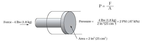
Pressure is the amount of force (in pounds) exerted on an object or a substance divided by the area (in square inches) over which the force is exerted. Although pressures are measured and specified in different ways, the use of pounds per square inch (PSI) is the most common. Force can also be calculated by multiplying the pressure by the area. In transmitting pressure through a confined liquid, some sort of movable member (e.g., a piston) is used to apply the pressure.
To determine the intensity of the force or pressure being applied to the system, the force is divided by the sealed area of the movable member:
|
|
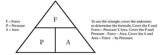
Figure 1-16 Force-Area-Pressure Triangle
|
Force = Pressure X Area |
Figure 1-17 Force-Area-Pressure Formulas
Mechanical forces can be multiplied using hydraulics. The determining factor for force multiplication is the surface area on which hydraulic pressure is applied. Since pressure is transmitted equally throughout a confined liquid, if the piston in a cylinder has more area than the movable member on which the force is applied, the output force will be greater than the input force. With a smaller cylinder area, the force would be less for the same system pressure, as shown in Figure 1-18.
|
|
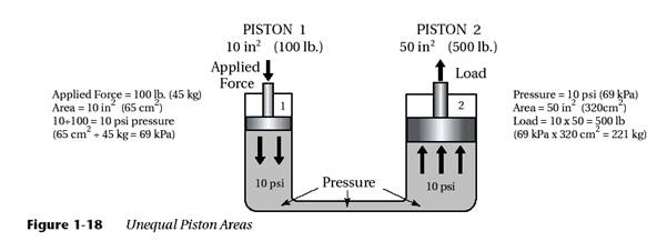
Figure 1-18 Unequal Piston Areas
In finding the area of a round piston’s surface area, the following formula is used:
|
pr 2 |
Using a 4 inch (10 cm) diameter piston, we would find the area or square inches (square centimeters) in the following manner:
- 1/2 of the diameter = the radius. In this case, the radius is 2 in (5 cm).
- Squaring the radius, by multiplying it by itself = 2 in X 2 in = 4 in (5 cm X 5 cm = 25 cm).
- Finally, multiplying the squared radius by pi will provide the area.
4 X 3.14 = 12.56 square inches
25 X 3.14 = 78.50 square centimeters
In a hydraulic system, pressure in pounds per square inch (PSI) or kilopascals (kPa) is exerted by fluid pressure acting over the flow area. The flow area of a cylinder can be expressed as the product of the piston area times the length of the piston’s stroke.
The tools required to work on a hydraulic system are normal hand tools. Included should be a set of tubing wrenches, and a flare and swage kit. Safety glasses are also required. Gauges are discussed in the next paragraph and you might want to have a gauge that you can tap into the system if you ever need to know the system pressure. Most systems do not have permanent gauges installed because, even though they are dampened, the needle vibrates so much they. Tend to wear out and become inaccurate.
In hydraulic systems there are two kinds of pressure: atmospheric and hydraulic. Atmospheric pressure 14.7 PSI, at sea level, is the pressure at work at all times on fluid reservoirs that are vented to the atmosphere. Hydraulic pressure is created by the fluid pump and acts on all internal passages on the discharge side of the pump.
Note: Pressure on a gauge is normally measured in pounds per square inch (PSI) or kilopascals (kPa)), thus the force will be expressed in units of pounds (kg), and the area expressed in units of square inches (cm2).
Pressure gauges used in hydraulic systems measure only pressure that is higher than the atmospheric pressure that surrounds them. Therefore, an unconnected pressure gauge has a reading of zero pounds per square inch gauge (0 psig). A reading of 100 on a hydraulic pressure gauge indicates a fluid pressure of 100 psig. If sea level atmospheric pressure (14.7) is added to the gauge pressure, the total is 114.7 psia (pounds per square inch, absolute).
Note: Normally, the distinction between psig (gauge) and psia is unimportant, so the term psi is commonly used in place of psig.
Pressure gauges are used to adjust pressure control valves to their required value, and to determine the forces being exerted by a cylinder or the torque of a hydraulic motor.
|
|
A pressure gauge is a device that measures the intensity of a force applied to a liquid. Two types of pressure gauge that are commonly used in hydraulic systems are the bourdon tube gauge and the plunger gauge.
A bourdon tube gauge, shown in Figure 1-20, basically consists of a dial face, calibrated in units of PSI and kPa, and a needle pointer attached through a linkage to a flexible metal coiled tube, called a bourdon tube. The bourdon tube is connected to system pressure. As pressure in a system rises, the bourdon tube tends to straighten out because of the difference in areas between its inside and outside diameters. This action causes the pointer to move and indicate the appropriate pressure on the dial face. Bourdon tube gauges are generally precision instruments with accuracies ranging from 0.1% to 3.0% of full scale.
|
|
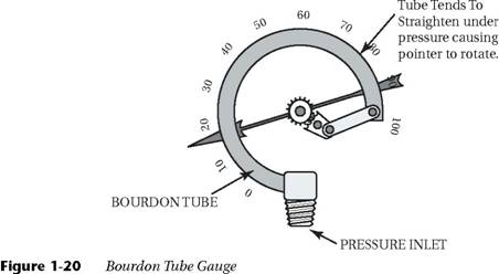
Figure 1-20 Bourdon Tube Gauge
A plunger gauge, shown in Figure 1-21, consists of a plunger connected to system pressure, a bias spring, pointer, and a scale calibrated in appropriate units of psi and kPa. As pressure in a system rises, the plunger is moved by the pressure acting against the force of the bias spring. This movement causes the pointer attached to the plunger to indicate the appropriate pressure on the scale.
|
|
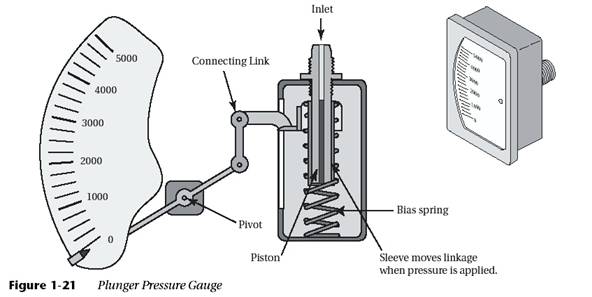
Figure 1-21 Plunger Pressure Gauge
In order to test various electrical components of systems a VOM and 12 VDC amp meter is required. A 12 VDC test light can be used for simple diagnostics but should not be used for accurate voltage and resistance testing.
|
|
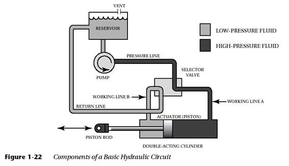
The components of a basic hydraulic circuit, as shown in Figure 1-22, are as follows:
- Reservoir: An area within the system that holds the hydraulic fluid. As the pump works to produce mechanical power, a supply of additional fluid is needed. The system receives this extra fluid from the reservoir.
- Pump: Mechanical power is converted into hydraulic power by the pump. The pump is required to move the fluid within the system.
- Lines (or conductors): Hydraulic power is transmitted by the fluid that is contained within the lines.
- Valves: Hydraulic power is regulated by valves. The valves determine whether the piston rod is extending or retracting.
- Actuator: Hydraulic power is converted to mechanical power by the actuator or piston. The actuator moves the fluid within the circuit to the work. The pressure of the fluid pushes up on the piston within the cylinder to lift the weight.