CHAPTER 2 – HYDRAULIC SYSTEM COMPONENTS
- 2-1 Vented Tanks/Reservoirs
- 2-2 Plumbing
- 2-3 Fluids
- 2-4 Pumps
- 2-5 Hydraulic Controls
- 2-6 Actuators or Cylinders
CHAPTER 2 – HYDRAULIC SYSTEM COMPONENTS
- Identify uses/function of hydraulic systems on RVs (power steering, hydraulic surge brakes, expandable room sections, shock absorbers, leveling systems).
- Identify hydraulic system components.
- Disassemble, clean and reassemble a hydraulic component.
- Identify the functions and types of reservoirs.
- Identify and select lines, fittings and couplings.
- Identify sealing devices and installation procedures.
- Identify hydraulic fluids, filters and additives.
- Identify system contaminants.
- Identify types of pumps and their construction.
- Identify hydraulic valves, cylinders and accessories.
A tank/reservoir is a container or containment area for keeping a supply of working fluid in a hydraulic system.
The functions of a reservoir are:
- To contain excess fluid resulting from system volume changes.
- To help cool the system.
- To replace fluid lost through system leakage.
- To help separate dirt and air from the fluid.
Tank/Reservoirs for the equipment typically found in an RV system are of the vented type, as shown in Figure 2-1. This means the tank/reservoir has a vent opening to the atmosphere, usually in the filler cap. Typically, the venting is provided by a breather cap, covering the opening where hydraulic fluid is added to the system. A magnet helps remove steel particles from the hydraulic fluid. Strainers and filters are used to keep the fluid clean.
|
|
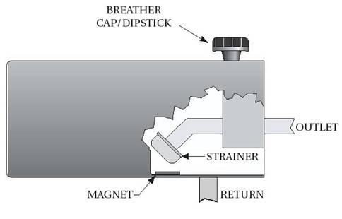
Figure 2-1 Parts of a Properly Designed Vented Tank/Reservoir
2-2 Plumbing
Most metal tubing on the high pressure side of the hydraulic system will be made of stainless steel or steel. The tubing on the high pressure side will be provided and installed by the component manufacturer. The tubing flares used on the high pressure side of the system will generally be flares of 37 degrees. Return lines are usually plastic tubing with compression fittings.
HWH hoses are specifically designed to meet HWH systems requirements.
Note: If hose replacement is needed, use the exact type and capacity of hose previously used. If you are unsure of the type of or capacity hydraulic hose to use, call HWH Technical Service.
Never use other manufacturers hoses.
Hose Construction
Hydraulic hoses consist of an elastometeric inner tube or of oil resistant synthetic rubber, with layers of reinforcing cord embedded in and/or bonded to the inner and outer tube. Depending on the type of hose, it may also have steel wire reinforcement and an oil-and weather-resistant synthetic rubber outer cover, as shown in Figure 2-2.
|
|
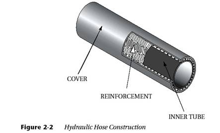
Figure 2-2 Hydraulic Hose Construction
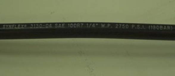
Hose Identification
HWH® hydraulic hoses, are legibly marked along their entire length, as shown in Figure 2-3.
|
|
Hose Application Factors
Fittings
Hydraulic hose is used with fittings. Hoses, with fittings attached, are commonly referred to as hose assemblies. Following installation instructions supplied by HWH provides adequate guidance on the hose and fittings to be used. Using fittings, hoses and swaging tools from different manufacturers is not recommended.
Fittings used for hydraulic hoses are numerous. It is important to get the correct fitting and hose combination for the intended application. When possible, the use of hose assemblies is recommended. Hose assemblies come with the fittings and hose pre-assembled. This eliminates confusion on hose and fitting compatibility.
The most common fitting is a swage-type fitting, as shown in Figure 2-4. A swage tool is required to assemble this type of fitting.
|
|
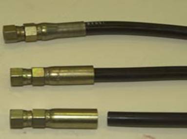
Figure 2-4 Swage Fitting
Flare Type Hose Fitting
Hydraulic systems commonly use the JIC (Joint Industry Conference standard) flare, as shown in Figure 2-5. These are 37o flares. The end of the tubing needs to be flared to mate with a fitting. The 45o single-flare and mating fittings are used in propane, natural gas and water systems, but should not be used for hydraulic application.
Compression Type Hose Fitting
This is a compression fitting that uses a ferrule that is compressed onto the tubing by the action of screwing the fitting parts together, as shown in Figure 2-5. The ferrule “bites” onto the tubing.
|
|
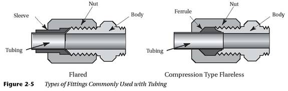
Figure 2-5 Types of Fittings Commonly Used with Tubing
No hydraulic system can properly operate without seals to hold the hydraulic fluid in the system when the system is under pressure. Seals also keep dirt and grime out of the system. While seals may appear to be simple objects when laying on the work bench or in your hand, they are really complex and precision parts that must be treated carefully if they are to do their job.
Hydraulic seals are used in two main applications. Static seals to seal fixed parts and dynamic seals to seal moving parts. Many types of seals are used in hydraulic systems. The type of seal used often depends on the type of hydraulic fluid used, the temperature and pressure of the application, whether the parts are dynamic or static, the speed of the moving parts and the amount of shock loading. Static seals are usually gaskets, but could be packings or O-rings. Dynamic seals involve rod and shaft seals and compression packings. Slight leakage at seals is permissible, as the leakage tends to lubricate the seals during use.
Note: Use only HWH parts for replacement seals and gaskets.
2-2.4.1 Types of Sealing Devices
O-rings
O-rings, depicted in Figure 2-6, are the most common type of seal. They come in all different sizes and materials. They are generally made of synthetic rubber and are compatible with most hydraulic fluids. O-rings can be used in static and dynamic applications.
Note: The only way to identify an O-ring is by the package it comes in. Be careful to match the O-ring to the fluid being used.
O-rings are designed to be used in grooves where they are compressed between two surfaces. In dynamic uses, they generally have a smooth surface to work against. They are not used across openings or where they must pass corners under pressure.
Back-Up Rings
Back-up rings, depicted in Figure 2-6, are used in static or dynamic situations. When O-rings are used in systems where the fluid pressure is 1500 PSI or higher, it is necessary to put a back-up ring behind the O-ring to keep it from being extruded in the grooves. Backup rings used to be made of leather, but now are primarily made of Thero plastics or Teflon®. They are installed behind the o-ring on the opposite side of the pressure. In an actuator, the piston would have a back-up ring on both sides of the O-ring since the pressure can come from either direction.
Gaskets
Gaskets, depicted in Figure 2-6, are only suitable for static applications. Gaskets are used in compression between two surfaces and seal by molding to imperfections between the two surfaces. Gaskets can be made from an array of materials and are available in multiple shapes and sizes.
U- and V- Packings
U- and V-packings, depicted in Figure 2-6, are dynamic seals. They are made of leather, synthetic and natural rubber, plastic and similar. These packings are installed with the open side, or lip, toward the system pressure so the system pressure will push the lip against the mating surface. This outward pushing will form a tight seal. These packings are made up of U- or V-shaped components.
|
|
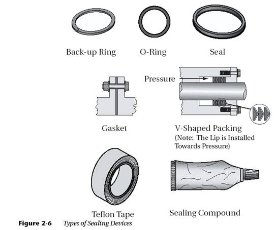
Figure 2-6 Types of Sealing Devices
Cup and Flange Packings
Cup packings are dynamic seals. These are made of synthetic rubber, plastic or similar. Surfaces are sealed by expansion of the lip or beveled edge of the packing. The most common use is at cylinder pistons and piston rods.
Sealing Compounds
Sealing compounds, such as thread lubricants and TeFon® tape should only be used on the male threads of pipe fittings and are never used on tubing fittings in a hydraulic system. Only the fluid in the system should be used to lubricate tubing fittings.
Hydraulic fluid is the medium by which power is transmitted from the pump to the mechanism that produces work. The fluid is one of the most important components of the hydraulic system. In fact, the majority of hydraulic system problems can be related to improper fluid use or fluid contaminants.
The system’s hydraulic fluid is important because it transmits the force applied to it to create work. In addition, the fluid must be able to lubricate the moving parts of the system, be stable over long periods of time, protect the systems parts from rust and corrosion, resist foaming and oxidation, and be capable of separating itself from air, water, and other contaminates. Finally, it must maintain its ability to flow (maintains its viscosity) throughout a wide range of temperatures.
Viscosity is the most important property of a hydraulic fluid. If the viscosity is too low, the fluid will be thin and could pass through the seals of the system. If the viscosity is too high, the equipment will be sluggish and will not function properly.
Most fluids have a tendency to get thin as the temperature rises and thicken as the temperature lowers. Therefore, finding the correct balance of a hydraulic fluid’s viscosity is important. The viscosity index helps individuals find the fluid that is balanced throughout a wide range of temperatures. Using a fluid with a high viscosity index will ensure the fluid is stable for a wide range of temperatures. The viscosity index is typically stated on the fluid container when it is purchased.
Some hydraulic fluids can handle the thrust pressures of the system better than others. Therefore it is important to use only HWH hydraulic oil.
Note: In an emergency call HWH Technical services before substituting any other oil.
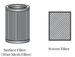
Servicing filters/screens are essential in keeping the hydraulic fluid in top condition. Dirt can be very harmful to a fluid because it acts as a catalyst for fluid decomposition and internal component wear. This is especially true if the dirt particles are ferrous, lead or copper. Filters or screens, depicted in Figure 2-7, usually remove a large percentage of dirt from a fluid stream. However, they do not remove all contaminates from the system; this is a maintenance function. One teaspoon of dust in 55 gallons of fluid is considered to be a dirty system. Even small amounts of contamination in a system can wear out a hydraulic components in just a matter of a few hours. Scored internal surfaces can result in excess leakage and poor performance of a component.
Some effects of contaminants in the hydraulic system:
|
|
|
Figure 2-7 Typical Filter Examples |
The pump is the primary component of the hydraulic system. The pump is what creates the flow of fluid and induces work as a result. All pumps create flow and operate on the principal of displacement. The fluid is taken into the pump, and displaced to another point.
To find out about a pump, you should always read its data plate. It may say “1 gal. per minute at 1200 rpm.” A positive displacement pump will be rated by its output at a given rpm. Usually, the pump is designed to run at this rpm or less. The data plate may also say “1500 PSI (10,000 kPa) rated” This means that the maximum pressure the pump is designed for is 1500 PSI (10,000 kPa) and it should be matched to a system that has a pressure relief setting at 1500 PSI (10,000 kPa) or less.
It is also very important that you understand that a pump doesn’t pump pressure. A pump pumps volume. In order to get pressure you have to restrict the output of the pump. Example: You hook a garden hose to the output of a pump. You tap a pressure gauge into the hose. You turn on the motorized pump and water flows out of the hose. The hose offers some restriction to the flow of water but for this lesson, the gauge reads zero. The pump is pumping so many gallons per minute, which is volume. Now put your thumb over the outlet of the hose and try to stop the water flow. The gauge is now reading pressure and the more you restrict the outflow the higher the pressure will go. The pump isn’t doing anything different. It’s still pumping out so many gallons per minute. The same thing is going to happen in the hydraulic system.
Displacement can be accomplished in one of two ways:
- Non-positive displacement
- Positive displacement
Most pumps used in hydraulic systems today are positive displacement pumps, as shown in Figure 2-8. Therefore we will not discuss non-positive displacement pumps. However, as a basic, a non-positive displacement pump, as shown in Figure 2-8, is a pump in which the inlet and outlet are hydraulically connected, so that the fluid can re-circulate in the pump when pressure builds. An example of a non-positive pump is a centrifugal water pump on a car’s cooling system.
A positive displacement pump is a pump that has the inlet sealed from the outlet. This holds the fluid within a system as it moves. As the fluid flows out of the pump, it is sealed against back-up, so it can not be drawn back into the pump. This sealing is the “positive” part of displacement. Without this sealing, the fluid could never overcome the resistance of the other components in the system.
|
|
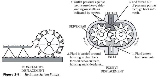
Figure 2-8 Hydraulic System Pumps
This pump will deliver fluid any time the inlet is kept supplied and the pump is driven. Positive displacement pumps must have a relieving device either internal to the pump or somewhere else in the system, or they will be damaged. This type of pump also has a pulsating type of output. The sealing mechanism of the positive displacement pump is primarily accomplished by the use of gears or pistons.
|
|
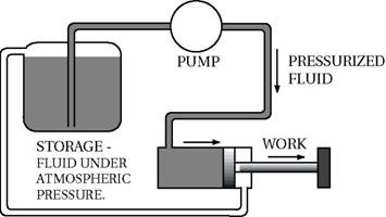
Figure 2-9 Pump Operation
2-4.1 Pump Types
The types of positive displacement pump are based on the sealing mechanism of the pump and how the positive displacement is accomplished. The basic types of positive displacement pumps are gear and piston pumps. Gear pumps are typically the only ones used in the RV industry.
2-4.1.1 Gear Pump
Gear pumps are the most commonly used pumps in the RV industry because they are simple and economical. The other types of pumps are generally cost prohibitive.
Gear pumps usually have two gears in mesh, closely fitted inside a housing. The drive shaft drives one gear, which in turn drives the other gear. Shaft bushings and machined surfaces or wear plates are used to seal in the working gears.
As the gears rotate and come out of mesh, they trap inlet fluid between the gear teeth and the housing. The trapped fluid is carried around to the outlet chamber. As the gears mesh again they form a seal which prevents fluid from backing up to the inlet. The fluid is forced out at the outlet port and sent through the system. This fluid is pushed out by the continuous flow of trapped fluid coming into the outlet chamber with each rotation of gears.
At the inlet side, gravity feeds in more fluid from the reservoir to replace that drawn out by the turning gears, as shown in Figure 2-10.
The main reason gear pumps are so popular is that they operate very smoothly.
|
|
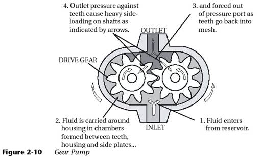
Figure 2-10 Gear Pump
Working energy transmitted hydraulically must be directed and under complete control at all times. If not under control, no useful work will be done or a machine might be destroyed. One of the advantages of hydraulics is that energy can be controlled relatively easily by using valves.
A valve is a mechanical device consisting of a body and an internal moving part which connects and disconnects passages within the body. The passages in hydraulic valves carry liquid. The action of the moving part controls maximum system pressure, direction of flow, and rate of flow.
Hydraulic energy can be applied to a piston type actuator, resulting in the performance of work. Once the actuator has reached full extension, the work is completed and there is no place for the fluid to go. A positive displacement pump will continue to try and deliver it’s rated output and the pressure will rise until damage is done to the system. A system pressure regulator or pressure control valve must be incorporated in the system to prevent this from happening.
Figure 2-11 shows an example of a pump supplying fluid to an actuator. In “A” the pressure in the system will be determined by the amount of resistance supplied by the object being moved. In “B” the pressure will be extreme because there is no pressure relief valve or a way for fluid to go back to the reservoir.
|
|
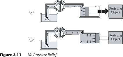
Figure 2-11 No Pressure Relief
A pressure control valve has an internal moving part which is operated by pressure. When the pressure in a system reaches a certain level, the internal moving part connects r disconnects passages in a valve body, allowing the liquid to follow another path.
Many times, the internal moving part of a pressure control valve is a spool. In one extreme position, the spool connects the passages, allowing the fluid to flow through the valve. In the other extreme, the passages are disconnected and the flow path through the valve is blocked.
In pressure control valves, the spool is held biased in one extreme position by a spring. If the passages are disconnected and the flow path through the body is blocked in its normal condition, the valve is designated a normally non-passing pressure control.
Pressure is sensed at the bottom of the spool by an internal passage connected to the primary passage. When system pressure overcomes the force of the spring, the spool moves and the passages are connected. Fluid is free to flow through the valve, see Figure 2-12.
|
|
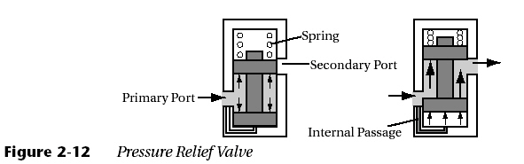
Figure 2-12 Pressure Relief Valve
Note: The fluid pressure used to operate the spool is known as pilot pressure. Pilot pressure is a common way of operating many types of hydraulic valves.
If the primary ports of this type of pressure valve were connected to the system, and the secondary port was connected to the reservoir, the flow from the pump could be directed back to reservoir when pressure applied to the pump becomes excessive. A normally non-passing pressure valve used in this manner is called a relief valve, as shown in Figure 2-13.
|
|
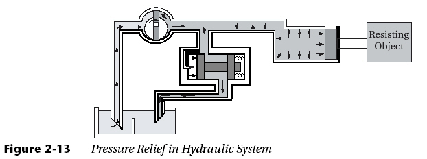
Figure 2-13 Pressure Relief in Hydraulic System
Note: Most pressure relief valves are adjustable by increasing and decreasing the spring tension as shown in Figure 2-14.
|
|
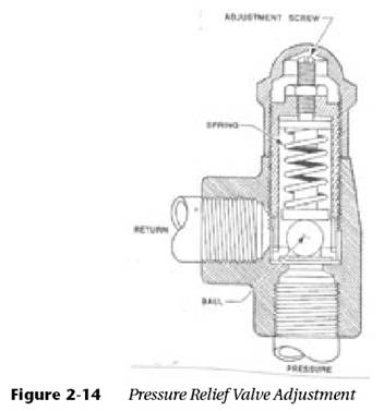
Figure 2-14 Pressure Relief Valve Adjustment
Flow control valves are used to route the fluid in the desired direction in a system to perform the work required. They can also be used to control the rate of flow in the system.
Figure 2-15 shows a one way valve, better known as a check valve. It consists of a body with a ball and a spring. In the direction you desire the fluid to flow, the fluid will move the ball back against the spring and uncover the passage. In the other direction the fluid and the spring will keep the ball on its seat, to block the flow.
|
|
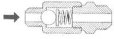
Figure 2-15 Check Valve
Figure 2-16 shows an orifice check valve. These valves are similar to a check valve except they usually have a cone instead of a ball. The cone has a drilled orifice that will allow free flow in one direction and restricted flow in the other. An orifice check valve could be installed in a leveling system where you want the jack to extend quickly and retract slowly, as shown in Figure 2-17.
|
|
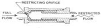
Figure 2-16 Orifice Check Valve
|
|
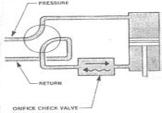
Figure 2-17 Orifice
Figure 2-18 shows a variable restrictor. A floor jack is a common example of a variable restrictor. The tapered valve can be screwed down on its seat to block the flow completely or the valve can be slowly moved off its seat to allow as much flow as desired.
|
|
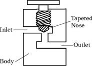
Figure 2-18 Variable Restrictor
Sometimes it is necessary to make sure one component works prior to another to avoid damage. An example might be insuring the leveling jacks on a motor home swing down from the horizontal position before they extend. This would be accomplished by the use of a sequence valve. See Figure 2-19.
Fluid from the outlet port would go to the “extend” side of the jack actuator and is blocked in view “A.” When the jack swings all the way down, it bumps a component and mechanically pushes the plunger in. The ball comes off the seat and allows fluid pressure to extend the jack actuator. This valve insures the jack has swung all the way down before it will extend.
|
|
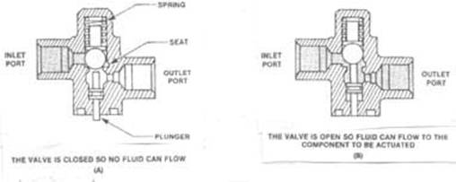
Figure 2-19 Sequence Valve
Some sequencing valves are operated by hydraulic pressure and are called priority valves. They are complex and won’t be covered in this book.
A selector valve, connects and disconnects internal passages within the valve body, which results in a control of fluid direction. This valve is used to determine which actuator(s) are going to move and in what direction. The selector valve spool can be moved either manually or electrically. In the manual mode there would be a lever attached directly or through linkage that the operator would move. The level might be labeled “UP” or “DOWN,” “IN” or “OUT.” In the electrical mode the spool would be moved by a solenoid. A typical selector valve or directional control valve is shown in Figure 2-20. The body of the valve has four port connected to internal passages. In the figure shown, the spool (dark portion) is in the neutral position and fluid from the pump is blocked. If the spool is moved to the right, the pump outlet passage is ported to passage “A” and fluid will flow to one side of an actuator. As the piston in the actuator moves, fluid is forced out to the return passage “B” which is now ported in the selector valve to return to return to the tank. If the spool is moved to the left, port “B” will be the pressure port and the actuator will move in the opposite direction. The hydraulic lines connected to ports “A” and “B” will alternate from pressure lines to return lines and will be known as working lines in the system.
|
|
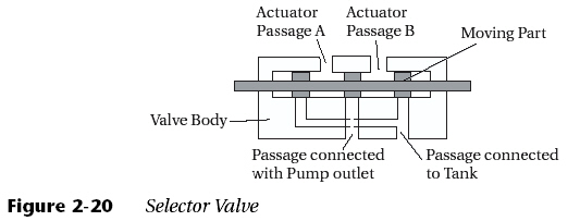
Figure 2-20 Selector Valve
Solenoid valves are operated electrically and are used to move a spool valve in a body, such as a selector valve or at as an “ON,” “OFF” valve. Figure 2-21 shows a solenoid valve in the de-energized or off position. The spool is in the spring loaded position shutting off the outlet passage. When voltage is applied to the coil, it becomes an electromagnet which causes the ferrous armature to be pulled toward the pole piece, sliding the spool and opening the passage. Solenoids are used extensively because they can be installed remotely and only require a switch in the panel for the operator.
|
|
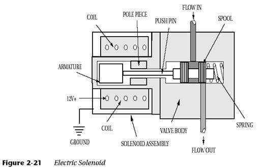
Figure 2-21 Electric Solenoid
The actuator does the work of the hydraulic system. It converts the fluid power from the pump to linear mechanical power. Actuators are the “arms” of the hydraulic system. Piston-type, linear actuators are the most common type used in recreation vehicles, and therefore will be the only type discussed herein.
There are two basic types of piston-type actuators. They are single-acting and double-acting, linear actuators.
These type of actuators only apply force in one direction. The hydraulic fluid passes through a manual or electrically operated selector valve under pressure and enters into one end of the actuator. This causes the piston to move, extending the ram, and work is performed. See Figure 2-22. Once the pressure is released, an outside force such as a spring or gravity would be used to return the cylinder to its starting position, as shown.
|
Fluid Flow Fluid Flow |
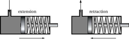
Figure 2-22 Single-Acting Actuator
These type of actuators apply force in both directions. The hydraulic fluid passes through a manual or electrically operated selector valve under pressure and enters into one end of the actuator. This causes the piston to move, extending the ram, and work is performed. See Figure 2-23. As the piston moves, fluid is forced out of the other end and is returned through the selector valve back to the reservoir or tank. When this selector valve is switched, fluid enters the other end of the actuator and the procedure is reversed. This allows two-way power.
|
|
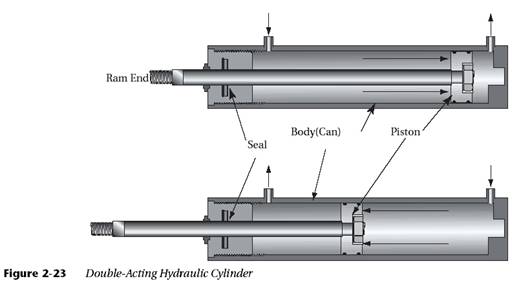
Figure 2-23 Double-Acting Hydraulic Cylinder
Types of Double-Acting Cylinders
A balanced double-acting cylinder has an equal area on both sides of the piston upon which the fluid (pressure) acts. Usually, the piston rod extends through the piston head on both sides. This gives equal working area on both sides of the piston and balances the working force of the cylinder whether it is extending or retracting, see Figure 2-24.
An unbalanced, or differential type, double-acting cylinder has unequal areas of force on each side of the piston, as shown in Figure 2-24. Typically, the rod side of the piston has less force than the “blank” side of the piston. This is because the rod fills up some of the volume not exposed to pressure. This type of cylinder is usually designed for a slower, more powerful stroke when it extends, and for a faster, less powerful stroke when it retracts. This application is the type found on RVs.
|
|
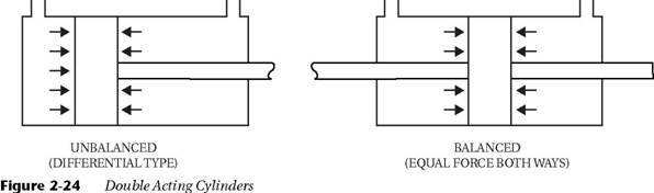
Figure 2-24 Double-Acting Cylinders