CHAPTER 3 – BASIC INFORMATION for PERFORMING HYDRAULIC SYSTEM MAINTENANCE
- 3-1 How a Hydraulic System Works
- 3-2 Schematic Symbols
- 3-3 Safety
- 3-4 RV Hydraulic Leveling Systems
- 3-5 Hydraulic Slide-Out Room Extensions
- 3-6 Bleeding the System
- 3-7 Servicing and Maintaining the Hydraulic System
CHAPTER 3 – BASIC INFORMATION for PERFORMING HYDRAULIC SYSTEM MAINTENANCE
- Identify hazards and safety requirements of hydraulic systems (pinch points, leaks, etc.).
- Identify basic hydraulic symbols specific to RV schematic symbols.
- Route hydraulic hose and piping.
- Identify common pump symbols.
- Identify valve, cylinder and accessory symbols (RV specific).
- Troubleshoot, clean, repair or replace leveling systems.
- Troubleshoot, clean, repair or replace lines, connectors and fittings.
Using the Figure 3-1, we can see the components and how they relate to each other to form a dual-acting hydraulic system. There is a supply line from the reservoir (1) through a filter (2) to the inlet of the pump (3). A pressure line comes out of the pump and goes through a pressure switch (4) to the selector valve (5). The lines going to and coming from the selector valve to the actuator (6) are going to alternate between pressure and return and therefore will be called the working lines. There will be pressure lines in one direction of the actuator and return lines in the other. The line going from the selector valve to the reservoir is always a return line. Remember, pressure lines are always pressure lines and return lines are always return lines, working lines alternate between pressure and return. Working lines are sometimes names by what they do when they are under pressure. “Up line,” “Down line,” “Extend line,” “Retract line,” etc.
|
|
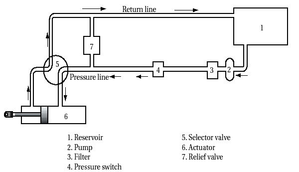
Figure 3-1 Typical Dual-Acting Hydraulic System (Pictorial Schematic)
- The electrically driven pump (3) starts turning and draws fluid from the reservoir (1) and pushes it out into the system through the selector valve (5). Keep in mind that the system is already full of fluid. Since fluid is incompressible, pressure will start to build and the actuator (6) will start to move immediately to the left.
- The fluid leaving the actuator (6) will go right back through the selector valve (5) to the reservoir (1).
- The fluid entering the pump (3) also goes through a filter (2) to keep debris out of the system.
- The actuator (6) is moving a heavy object. The pressure in the system will only be as high as it takes to move the object. The heavier the object, the higher the pressure.
- As soon as the actuator reaches it’s full travel, the fluid will have no place to go, so the pressure will build up immediately.
- The pressure reaches 1200 PSI and triggers the pressure switch relief valve (7).
- The pressure relief valve (7) set at 1200 PSI would function and bypass fluid back to the reservoir, to prevent damage to the system.
This is close to a typical system found in an RV.
|
|
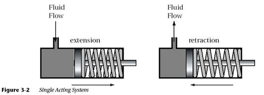
Figure 3-2 Single-Acting System
- A pump displaces volume and does not create pressure.
- When actuators are moving, the system pressure will only be as high as it takes to do the work.
- There must be no air in the system. Air is compressible. If air is in the system, the system will be spongy and may cause cavitation. Low hydraulic fluid may also cause cavitation because low fluid will allow air to enter the lines.
- On dual-acting systems, working lines alternate between pressure and return. The working lines are usually named by what they do under pressure (i.e., retract or extend).
- Moisture contaminates hydraulic fluid leading to rust and premature wear of components.
Figure 3-3 depicts symbols that will be used to identify components on some manufacturer’s schematics.
|
|
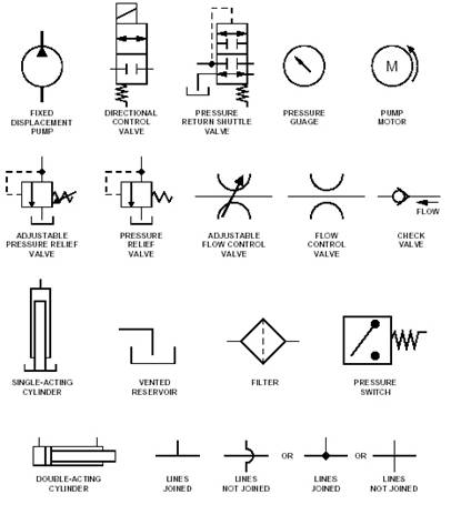
Figure 3-3 Schematic Symbols
Safety glasses need to be worn at all times when working on a hydraulic system. This is to protect eyes from dirt, metal chips, high pressure fluid leaks, etc. Additional personal protection equipment should be worn in accordance with OSHA or local government requirements.
When a leak is noted, stop the equipment, relieve the pressure and repair the leak(s) as quickly as possible.
When routing or re-routing hydraulic hoses and related electrical wires, be sure they are not exposed to engine exhaust or any high-temperature components of the vehicle. Hoses must be kept away from heat source. If that is not possible, an adequate heat shield must be used. Hoses and electrical wires must be protected from sharp edges and other sources of chaffing. Avoid kinking and twisting of hoses.
Note: Never place your hand or other parts of your body over or near a hydraulic leak. Hydraulic fluid under pressure may cut and penetrate the skin, causing injury or even death.
Do not over-extend any cylinder of the RV leveling system. If the weight of the vehicle is removed
from one or more wheels it places all the vehicle’s weight on the hydraulic cylinder(s). This may cause cylinder failure and/or instability of the RV leading to personal injury or vehicle damage.
Operate all control levers or mechanisms to insure that the hydraulic system has been completely relieved of pressure.
Components subjected to excessive pressure may fail.
Loosen lines and components in a hydraulic circuit slowly to relieve any trapped pressure.
Accidental or intentional release of trapped fluid in hydraulic circuits may cause components or the RV to malfunction or fall suddenly.
Leveling systems are not designed for supporting the weight of the RV for servicing. Never work under an improperly supported RV, adequately rated jack stands must be used.
Note: Many hydraulic fluids are extremely flammable. Do not smoke around or work around hydraulic fluid near an open flame.
Note: Some hydraulic fluids can irritate or burn when they come into contact with the skin or eyes.
Be aware some levelers may swing up or down abruptly, when a footpad clears the ground or when extending.
Note: Block the frame and tires of the RV securely before crawling under a vehicle. Do not use a leveling system or air suspension to support vehicle while under the vehicle or while changing tires. The vehicle may drop or move without warning, causing injury or death.
All hydraulic system components need to meet the requirements outlined in the component manufacturers installation instructions.
The hydraulic leveling system for RVs is a hydraulic system that uses the basic components we discussed at the beginning of this chapter. The leveling system has a reservoir, a pump, selector valves and actuators. As the fluid is pressurized, the actuator extends and works to level the RV.
Pivoting and straight-acting cylinders are available in capacities ranging from 6,000 lbs. (2750 kg.) per cylinder up to 24,000 lbs. (11000 kg.) per cylinder. Consult HWH specifications to determine the best combination of leveling cylinders for the application.
The leveling units should be mounted as close as possible to the front and rear axles. Check leveling unit and chassis manufacturer installation specifications for exact mounting position requirements.
Kick-down levelers must be positioned so that they swing up toward the rear when retracted. This allows the legs to kick up when the vehicle moves forward.
Each leveler must be mounted so that when it is in a vertical retracted position (not extended) there is adequate clearance between the ground and the footpad. Adequate clearance should be provided in accordance with component manufacturers specifications. Measurements should be determined when the vehicle is loaded to the stated GVWR.
The kick-down levelers are much easier to mount than the straight-acting leveler, especially in tight situations. Kick-down levelers are rarely damaged if the RV is inadvertently moved with the levelers down. The straight-acting jacks have a much larger footpad for greater stability. Make sure installations are done not only according to the component manufacturer’s instructions, but also chassis manufacturer’s recommendations.
The side of the frame is the best place to mount the levelers. Mounting brackets should be placed on the frame to allow cylinder adjustment upward or downward. It is important to place the bracket to give the system maximum ground clearance.
If a suitable mounting position cannot be located on the outer side of the frame, a special mounting adapter may be fabricated that fastens to the inside of the vehicle frame before the mounting bracket is welded or bolted on.
- Do not weld on vehicle unless approved by manufacturer.
- All batteries must be disconnected prior to welding in accordance with standard battery welding procedures.
- When the mounting bracket is welded to the frame, use caution to avoid all wiring, fuel lines or brake lines.
- Welds should not be made within 1/2 inch radius of the chassis frame rail.
- Check all chassis manufacturer and installation manual specifications for welding on chassis frame rails.
- Connecting welding ground to the part to be welded will minimize electronic failures.
- Mounting brackets often bolt right in, using holes provided by the chassis manufacturer.
- If drilling is required, use caution to avoid all wiring, fuel lines or brake lines.
- Bolt size and grade must meet or exceed leveler manufacturers specifications.
- Tightening of bolts should meet all manufacturers installation and torque specifications.
- In installations where the hose ends do not move in relation to each other, there needs to be slack in the hose to prevent strain. Hoses installed where they are tight or stretched tend to bulge and weaken under pressure.
|
|
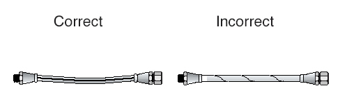
Figure 3-4 Avoid Taut Hose
- Prevent long loops by using angled fittings at the termination points. This helps to cut down on the length of hose needed. It also helps make a neater, overall installation. Pre-manufactured hose excess should be installed in a secure manner to prevent kinking.
|
Correct Incorrect
|
Figure 3-5 Avoid Loops
- Twists in the hosing can restrict the flow of hydraulic fluid and can cause the hose to weaken. Twists can also lead to loosened fittings. These situations can happen during installation or during equipment usage. Back-up wrenches must be used to avoid twisting of the hose during installation.
|
Correct Incorrect
|
Figure 3-6 Avoid Twisting
- Hoses should always be routed away from moving parts or sharp edges where they can rub or chafe. In some cases, protective clamps, brackets, or grommets may be needed to keep the hoses in their proper position(s).
- When routing hydraulic hoses, be sure they are not exposed to engine exhaust, or any high temperature components of the vehicle. It is recommended that hoses be located away from any heat source. If separation is not possible, you may need to construct a baffle with heat resistant material between the hose and heat source to protect the hose.
- The bend radius of a hose depends on the hose’s construction, size, and pressure. Hose manufacturers typically provide a minimum radius. Sharp bends in the hose can limit the system pressure, reduce the work force available, and can lead to hose rupture or other type of failure.
|
Correct Incorrect
|
Figure 3-7 Avoid Sharp Bends
- Support long runs of hydraulic hoses. This will also help protect the fittings from excessive strain. Ensure installation of hose support brackets meet manufacturers specifications.
- Ensure proper clearance is provided for all hoses during operation cycle (i.e., slide-out room extension and retraction).
Route and connect all system wiring as required by the device’s installation instructions and applicable code specifications.
Use the correct tools for all crimping operations and correct gauge wire for all extension splices. Exercise care when removing cable jackets and insulating coverings to insure wires are not damaged.
When routing electrical wires, be sure they are not exposed to engine, exhaust, high-temperature components, or any sharp edges on the vehicle.
Pump manifold assembly must be located in an area protected from the elements and high temperature components (i.e., exhaust). Location must be capable of supporting the weight and accessible for service.
It is recommended to have the pump as close to the power source as possible.
Figure 3-10 shows a typical schematic using hydraulic symbols. Notice the cylinders are plumbed in parallel, which is more normal. The dual cylinder portion of the schematic, shows a synchronizing valve in the system to cause the actuators to move together. In some systems the synchronizing valve is called a proportional valve. The cylinder extend and retract valves are solenoid selector valves discussed previously.
|
|
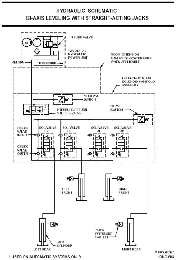
Figure 3-9 Typical Hydraulic Leveling System Symbol Schematic.
|
|
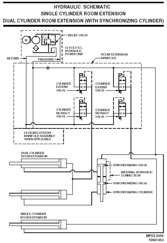
Figure 3-10 Typical Hydraulic Slide-Out Room Extension Symbol Schematic.
All adjustments or reinstallation of cylinders must be made in accordance with manufacturers specifications. Improper alignment of a cylinder may cause damage of the room or cylinder.
The slide-out room extension mechanism is critically important. If the adjustment of a slide-out room is even slightly off, the room may not seal completely in the extended or retracted position.
Cant is the leaning or tilt of an object, especially sideways. It is caused by improper alignment of cylinders, rails, and extensions caused by poor installation or wear and tear. Some slide-out room extensions may require periodic adjustment. Check manufacturer specifications for correcting this condition.
Bleeding of the system is the process of removing all air from the system and replacing it with appropriate hydraulic fluid. Air in cylinders and hydraulic lines will cause erratic system operation.
Prior to initiating the bleeding process, verify that all the fittings on the cylinder(s) and the manifold have been tightened to manufacturers specifications. The entire system must be filled with hydraulic fluid during the bleeding process. Check that the cylinders are fully retracted and fill the reservoir. It is important to follow procedures outline in HWH® Service Manuals for a specific system.
Note: Do not run the pump without fluid as damage to the pump may occur. Do not engage the pump motor for periods greater than thirty (30) seconds as pump damage may occur.
Hydraulic systems should be routinely checked as part of a regular scheduled vehicle maintenance program. It is recommended that the system be checked twice a year: in the spring, prior to the heavy travel season, and in the winter, prior to storage.
Note: During periods of vehicle inactivity and/or storage, the hydraulic system should be activated and cycled through the extending/ retracting procedures on a monthly basis to keep the actuators in good operating condition.
- Make sure the actuators are in the retracted position, remove the breather cap on the reservoir and check the fluid level in the reservoir.
- Clean dirt off breather caps, filler plugs and surrounding areas prior to opening the system.
- Use clean, lint-free towels to wipe off dip stick. The fluid level should be approximately 1" below the top of the reservoir or as indicated by the dip stick.
- This standard provides an adequate amount of fluid for the actuators to operate efficiently.
- If the fluid is below this level, add a sufficient amount to bring the level up to the operating standard.
Note: Do not mix fluid types.
- Check the wiring and wire connections throughout the system; these should be tight and secure. Repair and replace as necessary.
- Check the valve manifold for any evidence of hydraulic fluid leakage. Replace any seals as necessary.
- Check the hydraulic cylinders, hoses and assemblies for any damage and/ or leakage. Replace and/or repair as necessary. Verify that all mounting bolts have been tightened to manufacturers specifications.
- Keep the work area clean. This is especially important when disassembling components.
- Clean components prior to installing or reinstalling them in the system.
- To help prevent corrosion when left exposed to the atmosphere, lightly coat with lubricant as necessary.
- Inspect all pivot points and lubricate as necessary.